
Method, device and equipment for constructing entity model in virtual reality environment

A solid model and virtual reality technology, applied in the field of virtual reality, can solve problems such as increased workload, matching of 3D models, bumps and collisions, etc.

Inactive Publication Date: 2018-07-06
北京克一科技有限公司
View PDF10 Cites 1 Cited by
  • Summary
  • Abstract
  • Description
  • Claims
  • Application Information

AI Technical Summary

Problems solved by technology

[0003] Generally speaking, the establishment of a virtual reality 3D model needs to refer to the reference data provided by the architectural plan and related drawings. Due to the construction accuracy of the construction project and various restrictions on the site environment, there will always be inevitable problems in the specific architectural structure environment and design. Even if this data difference meets the accuracy requirements of engineering buildings, in a virtual reality environment that requires users to directly perform physical contact and visual measurement, it will still be unable to fully match the 3D model, which may cause users to experience visual and actual differences. The error of the distance may cause bumps, bumps or accidental touches
[0004] Generally speaking, in order to calibrate this deviation, in the existing scheme, the staff is usually required to wear a virtual reality head display, enter the construction environment, and measure the data deviation of each individual building unit by touching or using measurement tools. Calibration, in a slightly larger building environment, this calibration work needs to be repeated, the workload increases with the size and complexity of the building structure, and it takes a long time to be accurate, especially for non-standard buildings, such as slopes (Not at right angles to each other), the difficulty increases with curved and curved surfaces and other irregular shapes, often time-consuming but not ideal results

Method used


Image

  • Method, device and equipment for constructing entity model in virtual reality environment
  • Method, device and equipment for constructing entity model in virtual reality environment
  • Method, device and equipment for constructing entity model in virtual reality environment

Examples


Embodiment 1

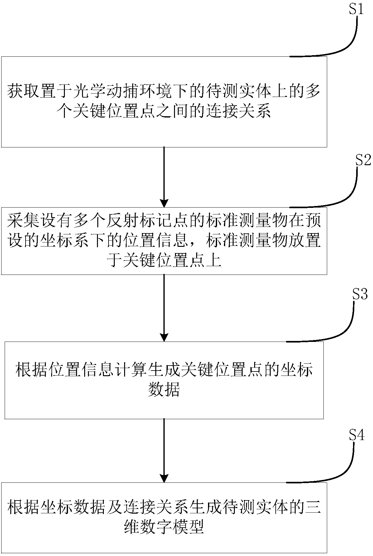
[0025] This embodiment provides a method for constructing a physical model in a virtual reality environment, such as figure 1 shown, including the following steps:

[0026] Step S1: Obtain the connection relationship between multiple key position points on the entity to be tested under the optical motion capture environment.

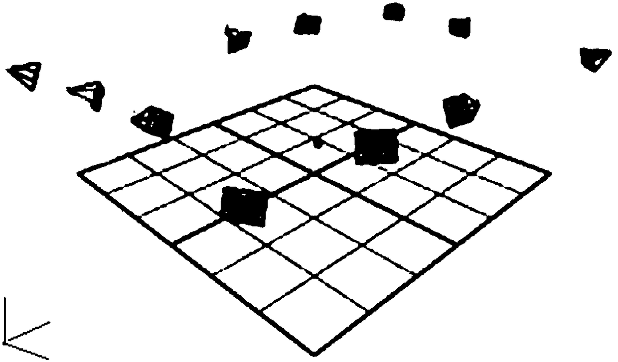
[0027] In the embodiment of the present invention, preferably, the overall physical structure of the entity to be tested is made open or semi-open in advance, and the whole of its internal and external structures is exposed to a complete optical motion capture environment, and the optical motion capture The environment is the same as that used later in the virtual reality environment. Such as figure 2 As shown, the so-called complete optical motion capture environment refers to a physical space constructed from different fixed angles by using multiple synchronous high-speed optical cameras, and all reflective markers within its range can be obtained b...

Embodiment 2

[0039] The present invention also provides a device for constructing a physical model in a virtual reality environment, such as Figure 6 shown, including:

[0040] Key position point connection relationship acquisition module 1: Acquire the connection relationship between multiple key position points on the entity to be tested under the optical motion capture environment; specifically, it can be used to perform step S1 of the above-mentioned embodiment 1, the specific process It has been described in detail in Embodiment 1 and will not be repeated here.

[0041] Standard measurement object position information acquisition module 2: used to collect the position information of a standard measurement object with multiple reflection marker points in a preset coordinate system, the standard measurement object is placed on the key position point; specifically , can be used to execute step S2 of the above-mentioned embodiment 1. The specific process has been described in detail in ...

Embodiment 3

[0045] Embodiments of the present invention also provide a device for constructing a physical model in a virtual reality environment, such as Figure 7 As shown, it includes: at least one processor 210 and a memory 220 communicatively connected to at least one processor; wherein, the memory stores instructions executable by at least one processor, and the instructions are executed by at least one processor so that at least one processing implement figure 1 method shown. The system may further include: an input unit 230 .

[0046] Processor 210, memory 220, and input unit 230 may be connected via bus 200 or other methods, Figure 7 Take connection via bus 200 as an example.

[0047] The memory 220, as a non-transitory computer-readable storage medium, can be used to store non-transitory software programs, non-transitory computer-executable programs and modules, as in the method corresponding to the method for constructing a physical model in a virtual reality environment in ...


PUM


Abstract

The invention discloses a method, a device and equipment for constructing an entity model in a virtual reality environment. The method comprises the steps of: acquiring a connection relationship amonga plurality of key position points on an entity to be tested which is placed in an optical motion capturing environment; acquiring position information of a standard measurement object with a plurality of reflective marking points in a preset coordinate system, wherein the standard measurement object is placed at one key position point; calculating to generate coordinate data of the key positionpoint according to the position information; and generating a three-dimensional digital model of the entity to be tested according to the coordinate data and the connection relationship. By adopting the method, the device and the equipment, a mode of pre-establishing the optical motion capturing environment is adopted, an optical motion capturing measurement tool is adopted and a marking means ofrecording the key position points quickly and accurately is employed for manufacturing a three-dimensional data model of the entity structure efficiently and precisely, and the time consumption is farless than that of the traditional physical measurement methods.

Description

technical field [0001] The invention relates to the field of virtual reality, in particular to a method, device and equipment for constructing a solid model in a virtual reality environment. Background technique [0002] In the virtual reality environment, in the instance that needs to be combined with the user's sense of touch, it is necessary to build a specific architectural structure environment, and make a digital model of a three-dimensional structure that is exactly the same as the architectural structure in the virtual reality environment, and make it consistent with the virtual reality environment. The location of the structure in . [0003] Generally speaking, the establishment of a virtual reality 3D model needs to refer to the reference data provided by the architectural plan and related drawings. Due to the construction accuracy of the construction project and various restrictions on the site environment, there will always be inevitable problems in the specific ...

Claims


Application Information

Patent Timeline
IPC IPC(8): G06T19/00G06F3/01
CPCG06F3/011G06T19/006
Inventor 王亚林
Owner 北京克一科技有限公司
Features
  • Generate Ideas
  • Intellectual Property
  • Life Sciences
  • Materials
  • Tech Scout
  • Unparalleled Data Quality
  • Higher Quality Content
  • 60% Fewer Hallucinations
Learn More