
Special welding device for power switch cabinet interlayer

A welding device and power switch technology, applied in the field of switchgear, can solve the problems of manual welding, poor welding quality, high labor intensity, etc., and achieve the effects of increasing welding stability and welding quality, fast welding speed, and high welding efficiency

Active Publication Date: 2017-01-04
YANCHENG POWER SUPPLY CO STATE GRID JIANGSU ELECTRIC POWER CO +4
View PDF6 Cites 0 Cited by
  • Summary
  • Abstract
  • Description
  • Claims
  • Application Information

AI Technical Summary

Problems solved by technology

[0003] In order to solve the above problems, the present invention provides a special welding device for the partition of the electric switch cabinet, which can solve the problems of complicated operation, high labor intensity, manual welding, slow welding speed, poor welding quality and problems in the existing processing method of the partition of the switch cabinet. Low welding efficiency and other problems can realize the automatic and fast welding function of the switch cabinet partition, which is easy to operate and does not require manual operation. It has the advantages of no manual welding, fast welding speed, good welding quality and high welding efficiency.

Method used


Image

  • Special welding device for power switch cabinet interlayer
  • Special welding device for power switch cabinet interlayer
  • Special welding device for power switch cabinet interlayer

Examples


Embodiment Construction

[0013] In order to make the technical means, creative features, goals and effects achieved by the present invention easy to understand, the present invention will be further described below in conjunction with specific illustrations.

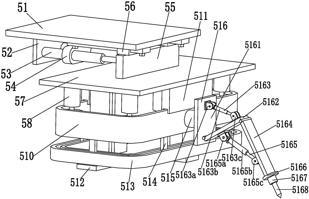
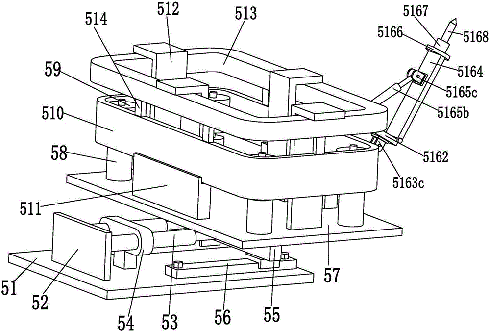
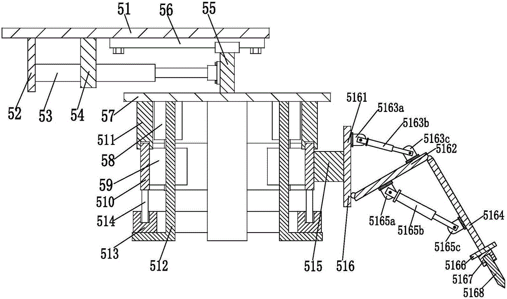
[0014] Such as Figure 1 to Figure 3 As shown, a special welding device for the compartment of a power switch cabinet includes a moving support plate 51, a vertical plate 52 is welded on the lower end of the mobile support plate 51, and two No. 3 hydraulic cylinders 53 are symmetrically installed on the inner wall of the vertical plate 52. The middle part of No. 3 hydraulic cylinder 53 is fixed on the T-shaped pillar 54, and T-shaped pillar 54 plays the function of fixedly supporting two No. 3 hydraulic cylinders 53. The top of the hydraulic cylinder 53 is equipped with a moving column 55 through the flange, and the upper end of the moving column 55 is symmetrically installed on two linear slide rails 56, and the two ends of each linear slide ra...


PUM


Abstract

The invention relates to a special welding device for a power switch cabinet interlayer. The special welding device comprises a moving support plate, a vertical plate is welded at the lower end of the moving support plate, two third hydraulic cylinders are symmetrically mounted on the inner wall of the vertical plate, the middles of the two third hydraulic cylinders are fixed on a T-shaped support column, so that the two third hydraulic cylinders are fixedly supported by the T-shaped support column, the T-shaped support column is welded on the moving support plate, a moving column is mounted at the top ends of the two third hydraulic cylinders through flanges, the upper end of the moving column is symmetrically mounted on two linear sliding rails, two ends of each linear sliding rail are mounted on the lower end surface of the moving support plate, the two third hydraulic cylinders can stably drive the moving column to bilaterally move through the two linear sliding rails, and a mounting plate is mounted at the lower end of the moving column. The special welding device can automatically and rapidly weld a switch cabinet interlayer, is simple and convenient to operate and has the advantages that the welding device is high in welding speed, good in welding quality and high in welding efficiency, and manual operation and manual welding are omitted and the like.

Description

technical field [0001] The invention relates to the technical field of switch cabinets, in particular to a special welding device for the compartment of a power switch cabinet. Background technique [0002] Switchgear is an electrical system that switches, controls, and protects electrical equipment during power generation, transmission, distribution, and power conversion. The main structure includes cabinets, load switches, contactors, various intermediate relays, and voltmeters. , ammeter, transformer and other components, and the cabinet body includes partitions, sealing plates, left and right side panels, bottom panels, top panels, doors, suspension rings and nameplates, etc. Among them, the cabinet body is the most important component, and the partitions are mainly The cabinet body is divided into blocks and layers to facilitate the modular and layered installation of electrical components. The existing partitions are mainly processed by manual welding. However, the exi...

Claims


Application Information

Patent Timeline
Patent Type & Authority Applications(China)
IPC IPC(8): B23K37/02
CPCB23K37/0211B23K37/0252
Inventor 王飞
Owner YANCHENG POWER SUPPLY CO STATE GRID JIANGSU ELECTRIC POWER CO
Learn More