Supercharge Your Innovation With Domain-Expert AI Agents!

Internal combustion locomotive radar installing and positioning method

A technology for installation and positioning of internal combustion locomotives, applied in the direction of assembly machines, metal processing equipment, manufacturing tools, etc., can solve problems affecting the normal operation of locomotives, achieve the effect of ensuring installation quality and improving work efficiency

Active Publication Date: 2017-01-04
CRRC DALIAN CO LTD
View PDF6 Cites 2 Cited by
  • Summary
  • Abstract
  • Description
  • Claims
  • Application Information

AI Technical Summary

Problems solved by technology

Affect the normal operation of the locomotive

Method used


Image

  • Internal combustion locomotive radar installing and positioning method
  • Internal combustion locomotive radar installing and positioning method
  • Internal combustion locomotive radar installing and positioning method

Examples


Embodiment Construction

[0026] The present invention will be further described below in conjunction with accompanying drawing.

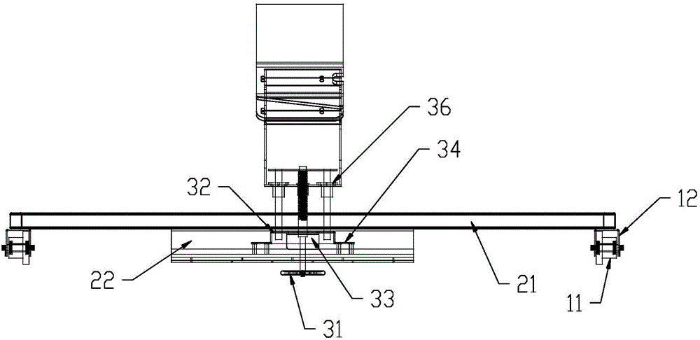
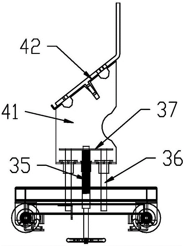
[0027] In the present invention, the structure of parts of the Harmony series diesel locomotive radar installation and positioning device is divided into four parts, including wheel assembly, base assembly, main body sliding and rising part assembly, and support part assembly.

[0028] Part 1: Wheel Assembly

[0029]

[0030] The wheel assembly consists of four groups distributed at the four corners of the base assembly. The wheel 11 is assembled on the wheel clamp 12 by cotter pins, and the wheel clamp 12 is welded on the four diagonal sides of the bottom of the square tube base 21 .

[0031] Part Two: Base Assembly

[0032]

[0033] Square tube base 21 is rectangular, and after slideway 23 is welded on the base support plate 22, base support plate 22 is welded on the square tube base 21, and main body sliding and rising part assembly part just can move certain dis...


PUM


Abstract

The invention discloses an internal combustion locomotive radar installing and positioning method. According to the method, a wheel assembly, a base assembly, a main body sliding and lifting part assembly and a supporting part assembly are involved. The wheel assembly is matched with the horizontal rail surface. A slide way is arranged on the base assembly. The main body sliding and lifting part assembly can move along the slide way. Meanwhile, the supporting part assembly is driven by a lead screw structure in the vertical direction to move up and down. The supporting part assembly is matched with a radar support assembly. The included angle between a supporting plate of the supporting part and the horizontal plane is 37.5 degrees. The effect that the included angle between the radar support assembly and the horizontal rail surface is 37.5 degrees can be guaranteed. The internal combustion locomotive radar installing and positioning method is suitable for vehicle radar installing and positioning, installation is fast and convenient, and positioning is accurate.

Description

technical field [0001] The invention relates to the technical field of communication equipment for diesel locomotives. Background technique [0002] According to the technical requirements of the radar installation of the Harmony series diesel locomotive, after manually adjusting the angle of the radar bracket assembly, the pads are installed on the positioning pins. It is difficult to ensure that the angle between the bottom surface of the radar bracket assembly and the horizontal rail surface is an accurate angle. [0003] The radar device is installed manually. Install the radar with a mallet and an angle meter to adjust the angle of the radar bracket assembly. After the angle adjustment is completed, install the pad on the positioning pin. It is required to accurately ensure that the angle between the bottom surface of the radar bracket assembly and the horizontal rail surface is 37.5°±0.25°, but it is very difficult. It is difficult to guarantee this angle. [0004] O...

Claims


Application Information

Patent Timeline
Patent Type & Authority Applications(China)
IPC IPC(8): B23P21/00
CPCB23P21/002
Inventor 滕微刘云翔苗颖超李鹏飞
Owner CRRC DALIAN CO LTD
Features
  • R&D
  • Intellectual Property
  • Life Sciences
  • Materials
  • Tech Scout
  • Unparalleled Data Quality
  • Higher Quality Content
  • 60% Fewer Hallucinations
Learn More