A wind power blade mold root flange device and using method thereof

A wind turbine blade and flange technology is applied in the field of wind turbine blade mold root flange device, which can solve problems such as accident risk, damage to the root base, weaken the strength of the base, etc. Insufficient effect

Active Publication Date: 2018-08-07
连云港双菱风电设备科技有限公司
View PDF4 Cites 0 Cited by
  • Summary
  • Abstract
  • Description
  • Claims
  • Application Information

AI Technical Summary

Problems solved by technology

With the increasing development of the wind energy industry at home and abroad, there are more and more types of wind power blades. At present, the installation of blades and fans is generally connected by bolts. Usually, after the blades are manufactured, they are installed and connected by punching holes at the root. Bolts, this method is no problem when the root bears a small load or the blade size is relatively small and the weight is relatively small, but as the power of the wind turbine increases, the length of the matching blade and its root size also change It is getting bigger and bigger, and the weight is also increasing, which requires the root of the blade to be able to withstand greater loads, and the performance requirements of the root of the blade are also higher, and this method of installing bolts by drilling holes in the root of the blade damages the root. Substrate, which weakens the strength of the substrate, there is a risk of accidents in the case of large blades or roots with large size and weight

Method used


Image

  • A wind power blade mold root flange device and using method thereof
  • A wind power blade mold root flange device and using method thereof
  • A wind power blade mold root flange device and using method thereof

Examples


Embodiment Construction

[0018] The technical solution of this patent will be further described in detail below in conjunction with specific embodiments.

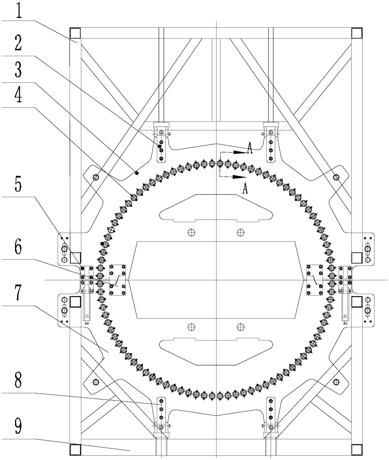
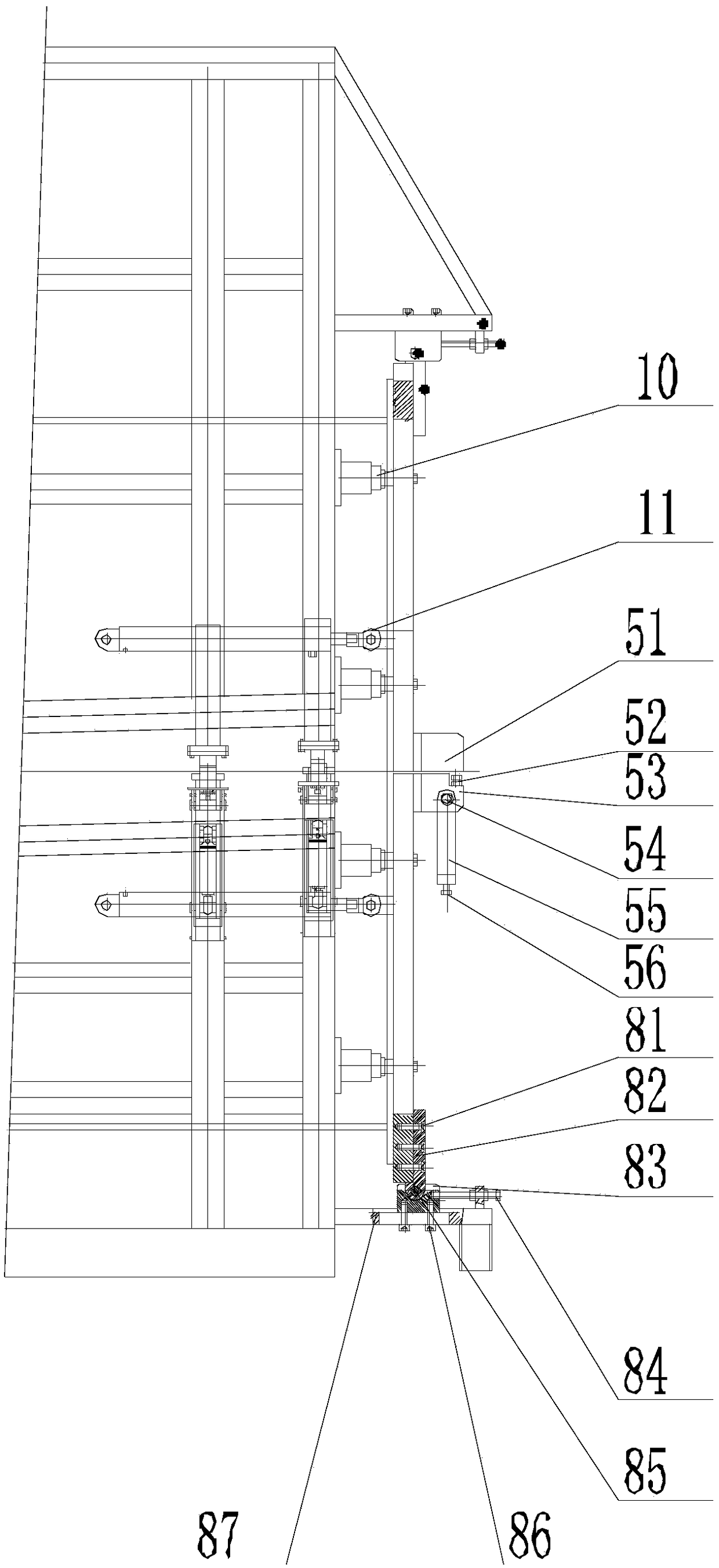
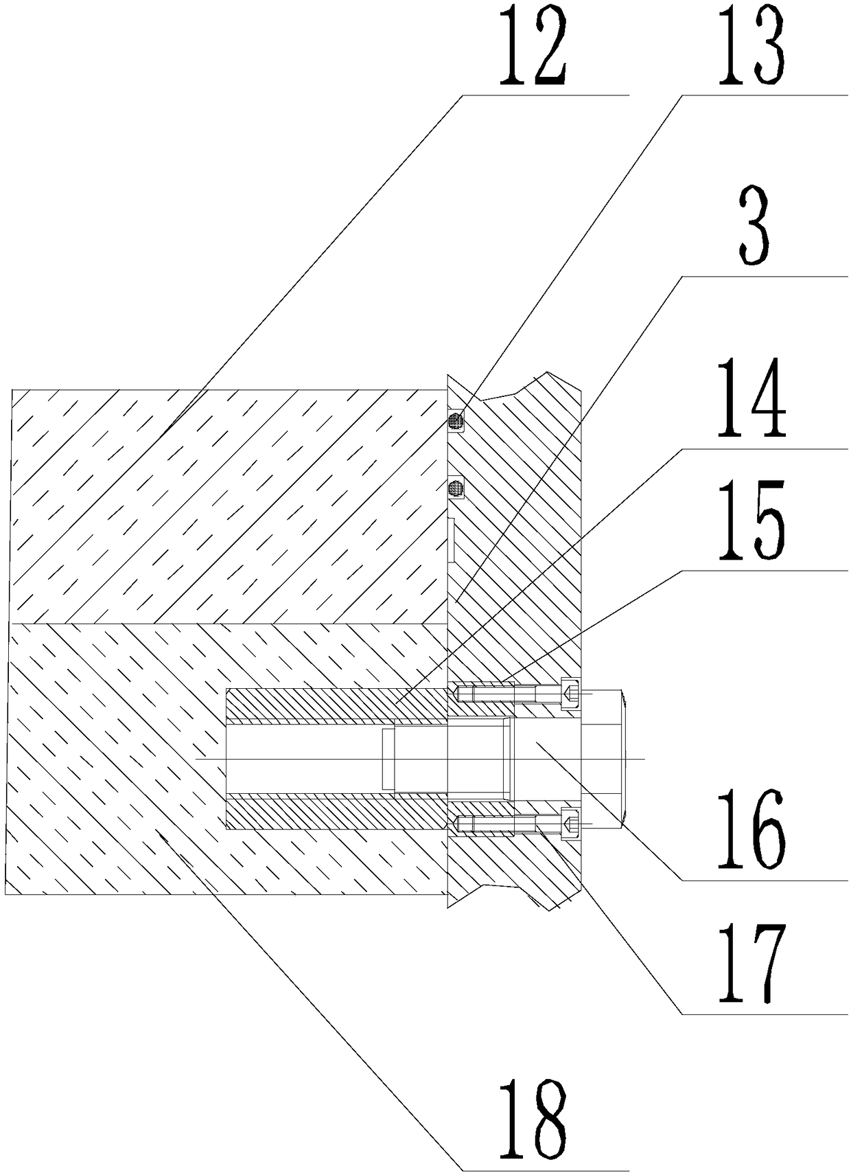
[0019] see Figure 1-3 , a flange device at the root of a wind power blade mold, comprising an upper mold steel flange 3, an overturning connection device, a lower mold steel flange 7, a pre-embedded bolt mechanism 4, a locking device 5, a positioning device 6, a positioning support device 10 and Overturning oil cylinder device 11, described overturning connecting device comprises the first overturning connecting device 2 and the second overturning connecting device 8, the upper die steel flange 3 and the lower die steel flange 7 are semicircular and the upper die steel flange 3 and the lower die steel flange The center of the mold steel flange 7 coincides, the two sides of the center of the upper mold steel flange 3 and the lower mold steel flange 7 are provided with a locking device 5, and the inner side of the locking device 5 is provided with a...


PUM


Abstract

The invention discloses a wind power vane mold root flange device. The wind power vane mold root flange device comprises an upper mold steel flange, overturning connection devices, a lower mold steel flange, an embedded bolt mechanism, locking devices, positioning devices, positioning supporting devices and overturning oil cylinder devices. The overturning connection devices comprise the first overturning connection devices and the second overturning connection devices, and the embedded bolt mechanism comprises embedded bolt sleeves, fixing sleeves, connection bolts and first screws. The invention further discloses a using method of the device. The device is easy and convenient to operate, the fixing sleeves are arranged in the upper mold steel flange and the lower mold steel flange, and the perpendicularity of the embedded bolt sleeves and the surfaces of the steel flanges is ensured, so that the perpendicularity of the connection bolts and the end faces of vanes is ensured, and the connection strength of the vanes and a vane draught fan is ensured; the method that traditionally, bolt sleeves are installed by perforating vanes is improved, and the problem of insufficient connection strength caused by perforating the roots of vanes is solved.

Description

technical field [0001] The invention relates to a flange device, in particular to a flange device at the root of a wind power blade mold. Background technique [0002] In the 21st century, various countries in the world began to develop environmentally friendly and renewable new energy sources, and wind energy is one of them. With the increasing development of the wind energy industry at home and abroad, there are more and more types of wind power blades. At present, the installation of blades and fans is generally connected by bolts. Usually, after the blades are manufactured, they are installed and connected by punching holes at the root. Bolts, this method is no problem when the root bears a small load or the blade is relatively small in size and weight. However, as the power of the wind turbine increases, the length of the matching blade and its root size will also change. It is getting bigger and bigger, and the weight is also increasing, which requires the blade root ...

Claims


Application Information

Patent Timeline
Patent Type & Authority Patents(China)
IPC IPC(8): B29C33/30
CPCB29C33/305
Inventor 王辉徐庆臣安建民周敏
Owner 连云港双菱风电设备科技有限公司
Why Eureka
Try Eureka