Vertical high-precision post-processing machine for plastic pipes
What is Al technical title?
Al technical title is built by PatSnap Al team. It summarizes the technical point description of the patent document.
A plastic pipe, high-precision technology, applied in metal processing and other directions, can solve problems such as affecting production efficiency, high manufacturing cost, and large volume.
Active Publication Date: 2018-06-08
YONGGAO CO LTD
View PDF4 Cites 0 Cited by
Summary
Abstract
Description
Claims
Application Information
AI Technical Summary
This helps you quickly interpret patents by identifying the three key elements:
Problems solved by technology
Method used
Benefits of technology
Problems solved by technology
[0002] After some large plastic pipes are injection molded and cooled, the surface will partially shrink, resulting in uneven surface roundness, or some plastic pipes have a slightly larger outer diameter after injection molding, which cannot meet the use requirements. Requires secondary processing of the tubing to achieve uniform roundness on the outer surface or an outer diameter of the specified size
The existing technology is to put the injection-molded plastic pipe on the machine tool for secondary processing, and the processing efficiency is low, which affects the production efficiency, and the processing of large-diameter pipes requires a large machine tool, which is large in size, takes up a lot of space, and the manufacturing cost high
Method used
Image
Click on the blue label to locate the original text in one second.
Reading with bidirectional positioning of images and text.
Examples
Embodiment Construction
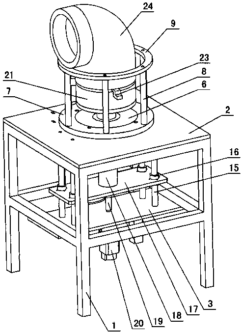
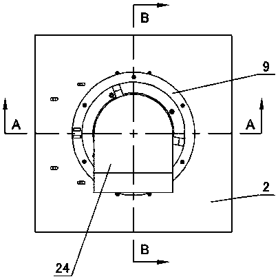
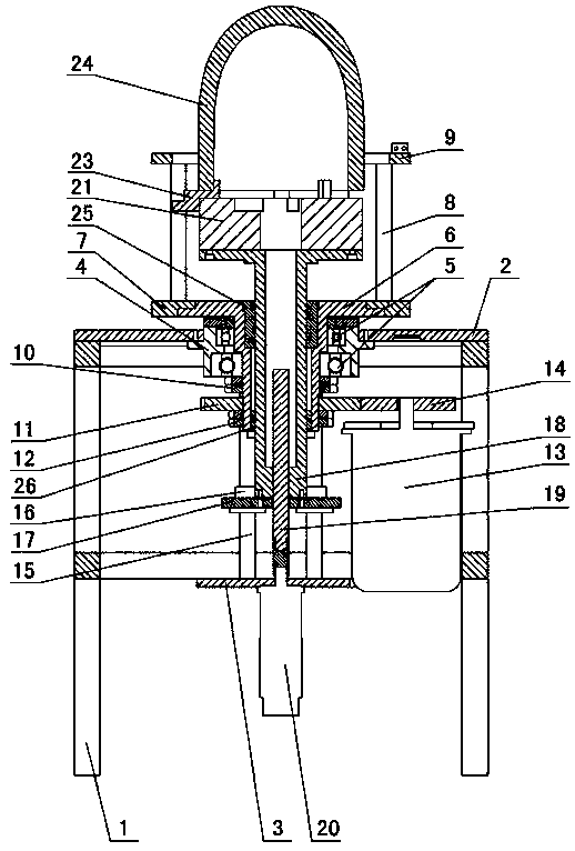
[0012] The invention relates to a vertical high-precision post-processing machine for plastic pipes, such as figure 1 — Figure 5 As shown, it is characterized in that it includes a frame 1, an upper fixing plate 2 and a lower fixing plate 3 are arranged on the frame, a bearing sleeve 4 is arranged in the upper fixing plate, a bearing 5 is arranged in the bearing sleeve, and the inner wall of the bearing is connected to a copper sleeve shaft 6 , the upper end of the copper sleeve shaft is provided with a knife rest support plate 7, a knife rest support rod 8 is arranged on the knife rest support plate, a knife rest ring 9 is arranged on the knife rest support rod, a blade is arranged on the knife rest ring, and a blade is set on the copper sleeve shaft 6 outer walls A bearing lock nut 10, a driven gear 11 and a gear lock nut 12 are arranged in sequence at the lower end of the bearing 5, and a large motor 13 is set in the frame 1, and the output shaft of the large motor is conn...
PUM
Abstract
A vertical high-precision post processor for a plastic pipe is characterized by comprising a rack; an upper fixing plate and a lower fixing plate are arranged on the rack, a bearing bush is arranged in the upper fixing plate, bearings are arranged in the bearing bush, the inner walls of the bearings are connected with a copper bush shaft, a tool rest supporting plate is arranged outside the upper end of the copper bush shaft, tool rest supporting rods are arranged on the tool rest supporting plate, a tool rest ring is arranged on the tool rest supporting rods, and blades are arranged on the tool rest ring; bearing locking nuts, a driven gear and gear locking nuts are arranged on the part, located at the lower ends of the bearings, of the outer wall of the copper bush shaft in sequence; a large motor is arranged in the rack and connected with a driving gear, the driving gear is meshed with the driven gear, guide columns are arranged between the upper fixing plate and the lower fixing plate, guide sleeves are arranged on the guide columns, a sliding plate is arranged on the guide sleeves, a vertical adjusting block is arranged on the sliding plate, communicated screw holes are formed in the vertical adjusting block and the sliding plate, a screw is arranged in the screw holes, a small motor is arranged below the lower fixing plate, an output shaft of the small motor is connected with the screw, a chuck is arranged on the vertical adjusting block, clamping grooves are formed in the chuck, clamping bases are arranged in the clamping grooves, and the clamping bases are matched with the inner wall of the plastic pipe.
Description
technical field [0001] The invention relates to a post-processing machine for plastic pipes, in particular to a vertical high-precision post-processing machine for plastic pipes. Background technique [0002] After some large plastic pipes are injection molded and cooled, the surface will partially shrink, resulting in uneven surface roundness, or some plastic pipes have a slightly larger outer diameter after injection molding, which cannot meet the use requirements. Secondary processing of the tubing is required to achieve uniform roundness on the outer surface or to a specified outer diameter. The existing technology is to put the injection-molded plastic pipe on the machine tool for secondary processing, and the processing efficiency is low, which affects the production efficiency, and the processing of large-diameter pipes requires a large machine tool, which is large in size, takes up a lot of space, and the manufacturing cost high. Contents of the invention [0003...
Claims
Application Information
Patent Timeline
Application Date:The date an application was filed.
Publication Date:The date a patent or application was officially published.
First Publication Date:The earliest publication date of a patent with the same application number.
Issue Date:Publication date of the patent grant document.
PCT Entry Date:The Entry date of PCT National Phase.
Estimated Expiry Date:The statutory expiry date of a patent right according to the Patent Law, and it is the longest term of protection that the patent right can achieve without the termination of the patent right due to other reasons(Term extension factor has been taken into account ).
Invalid Date:Actual expiry date is based on effective date or publication date of legal transaction data of invalid patent.