An automobile electro-hydraulic emergency braking device and control method

An emergency braking and electro-hydraulic technology, applied in the direction of automatic starting devices, brakes, braking components, etc., can solve the problems of loss of braking efficiency, decrease of friction factor, and debatable braking effect, and achieve the effect of preventing accidents

Active Publication Date: 2018-09-18
JIANGSU UNIV OF TECH
View PDF8 Cites 1 Cited by
  • Summary
  • Abstract
  • Description
  • Claims
  • Application Information

AI Technical Summary

Problems solved by technology

However, this kind of frictional braking will lead to a substantial increase in the temperature of the brake, resulting in a decrease in its friction coefficient, aggravated wear, and a dangerous thermal decay phenomenon of partial or even complete loss of braking performance.
[0003] At the same time, the car ECU will automatically start the ABS control during the braking process to prevent the car from skidding or rolling over, but this will not lead to a significant reduction in the braking distance
[0004] Chinese patents CN 102126486 A and CN 103522996 A disclose two kinds of auxiliary braking devices, but the braking effect is open to question, especially the emergency braking effect

Method used


Image

  • An automobile electro-hydraulic emergency braking device and control method
  • An automobile electro-hydraulic emergency braking device and control method
  • An automobile electro-hydraulic emergency braking device and control method

Examples


Embodiment Construction

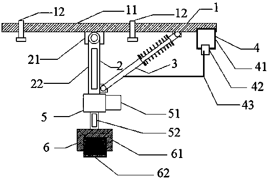
[0035] Such as Figure 1-5 As shown, an automobile electro-hydraulic emergency braking device is distributed on the left and right sides of the chassis, and is located between the front and rear wheels. The electro-hydraulic emergency braking device specifically includes a chassis fastening plate 1, a support rod Part 2, hydraulic control telescopic rod part 3, hydraulic control part 4, steering part 5, brake foot 6;

[0036] The chassis fastening plate 1 includes: a fastening plate 11 and a fastening bolt 12;

[0037] The support rod 2 includes: a support seat 21 and a support rod 22;

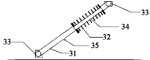
[0038] The hydraulically controlled telescopic rod 3 includes: a telescopic cylinder 31, a spring 32, a fixing seat 33 and a telescopic rod 34;

[0039] The hydraulic control part 4 includes: an oil tank 41, an oil pump 42 and an oil pipe 43;

[0040] The steering component 5 includes: a steering motor 51 and a steering column 52;

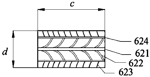
[0041] The brake foot 6 includes: a fastening cylinder 61...


PUM


Abstract

The invention relates to the technical field of automobile emergency braking, in particular to an automobile electro-hydraulic emergency braking device. The electro-hydraulic emergency braking device comprises a chassis fastening plate, a supporting rod piece, a hydraulic control telescopic rod piece, a hydraulic control component, a steering component and a braking foot. A fastening plate body is fixed to an automobile chassis through fastening bolts. One end of a supporting rod is connected with the fastening plate body, the other end of the supporting rod is connected with the steering component, and the supporting rod can rotate around a supporting seat by 0 degree to 90 degrees. A telescopic barrel is communicated with an oil pipe, and the telescopic motion speed and the telescopic force of a telescopic rod are controlled. The motion state of an oil pump is controlled by an emergency braking ECU. A steering motor is controlled by the emergency braking ECU, meanwhile, rotation of a steering column is driven, and rotation of the braking foot is driven by rotation of the steering column. In the braking process, the included angle between the automobile speed direction and the front-wheel steering direction is observed, the angle of the braking foot is adjusted, and an automobile is prevented from sideslipping and even being rolled over.

Description

technical field [0001] The invention relates to the technical field of automobile emergency braking, in particular to an automobile electro-hydraulic emergency braking device and a control method. Background technique [0002] The braking system is one of the most critical and important components of a car, which is directly related to the safety of people's lives and property. The main brake of the vehicle generally adopts drum or disc friction braking method, which converts the kinetic energy and potential energy of the vehicle into heat energy through friction, so as to realize the purpose of deceleration or braking of the vehicle. However, this kind of frictional braking will cause the temperature of the brake to increase significantly, resulting in a decrease in its friction coefficient, aggravated wear, and a dangerous thermal decay phenomenon of partial or even complete loss of braking performance. [0003] At the same time, the ECU of the car will automatically star...

Claims


Application Information

Patent Timeline
Patent Type & Authority Patents(China)
IPC IPC(8): B60T1/14B60T7/12
CPCB60T1/14B60T7/12
Inventor 李波贝绍轶倪彰张兰春郑焱赵景波
Owner JIANGSU UNIV OF TECH
Why Eureka
Try Eureka