Armrest structure and aircraft seat group thereof
A technology of aircraft seats and armrests, which is applied to the layout of seats and other directions, can solve the problems of hands touching each other and the distance between armrests being close to each other, and achieve the effect of solving troubles and improving the appearance
- Summary
- Abstract
- Description
- Claims
- Application Information
AI Technical Summary
Problems solved by technology
Method used
Image

Examples
Embodiment 1
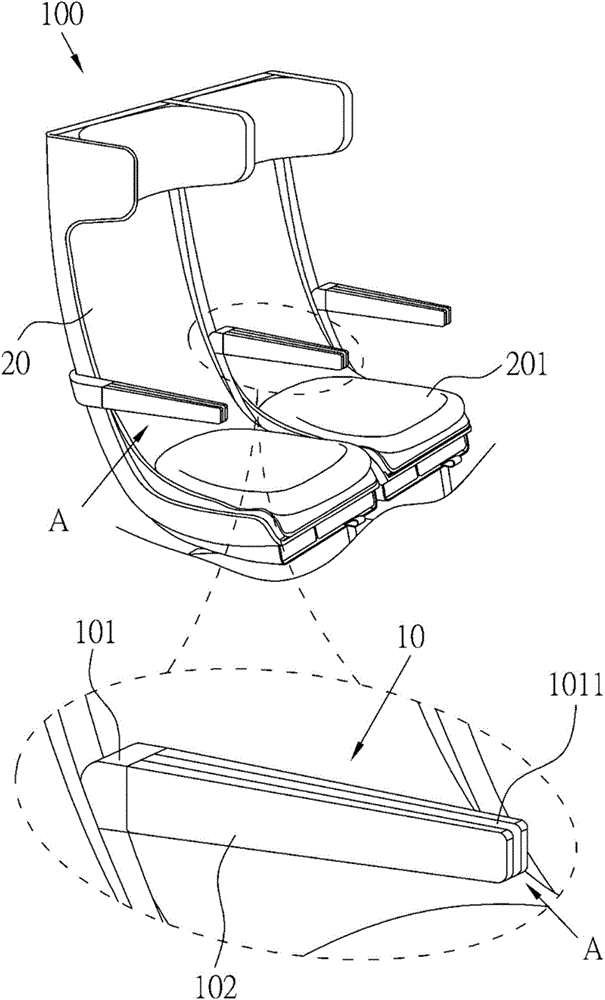
[0044] refer to figure 1 , 2 As shown, it is the first schematic diagram and the second schematic diagram of Embodiment 1 of the aircraft seat group of the present invention. Wherein, the aircraft seat group 100 is provided with the armrest structure 10 of the present invention for passengers to properly place their hands.
[0045] As shown in the figure, the aircraft seat set 100 includes an armrest structure 10 and an aircraft seat 20 . Wherein the number of aircraft seats 20 can be two, three or more, and the armrest structure 10 is correspondingly one, two or more. In this embodiment, two aircraft seats 20 and one armrest structure 10 are taken as an example for illustration, but it is not limited thereto.
[0046] Two aircraft seats 20 are arranged adjacently. The armrest structure 10 includes an armrest body 101 and two supporting plates 102 . The armrest body 101 is disposed between two aircraft seats 20 . The shape of the two supporting plates 102 is correspondin...
Embodiment 2
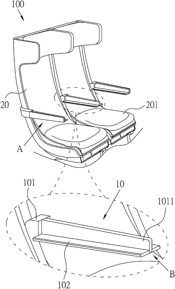
[0053] refer to Figure 4 , 5 , which are respectively the first schematic diagram and the second schematic diagram of Embodiment 2 of the aircraft seat group of the present invention. In this embodiment, the configuration of each component is similar to that of Embodiment 1, and the similarities will not be repeated here. The main difference between the present embodiment and the first embodiment lies in the transformation manner of the supporting plate 102 from the first position A to the second position B.
[0054] Furthermore, in this embodiment, the width of the supporting plate 102 can be smaller than the width of the armrest body 101 . In addition, one end of each supporting plate 102 and the other side close to the supporting plate 102 are pivotally disposed in the concave portion 1011 . Wherein, the other side of the support plate 102 refers to the side away from the seat cushion 201 of the aircraft seat 20 .
[0055] Therefore, the passenger on the aircraft seat ...
Embodiment 3
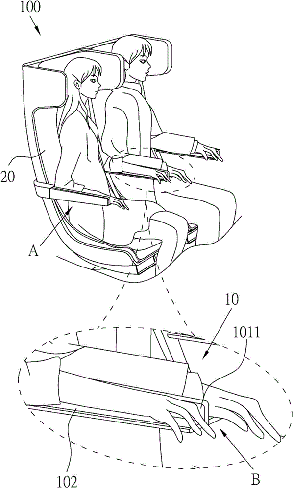
[0057] refer to Figure 6 , which is a schematic diagram of Embodiment 3 of the aircraft seat group of the present invention. In this embodiment, the configuration of each component is similar to that of the foregoing embodiments, and the similarities will not be repeated here. The main difference between this embodiment and Embodiment 1 is that the supporting plate 102 is converted from the first position A to the second position B, and the main difference from the second embodiment is that the supporting plate 102 is changed from the first position A to the second position B. After the transformation from the first position A to the second position B, the space between the two supporting plates 102 and the armrest body 101 forms an inverted T shape.
[0058] In this embodiment, the width of the supporting plate 102 may correspond to (for example be equal to) the width of the armrest body 101 . In addition, as in the previous embodiment, one end of each supporting plate 102...
PUM
 Abstract
Description
Claims
Application Information
 - R&D
- Intellectual Property
- Life Sciences
- Materials
- Tech Scout
- Unparalleled Data Quality
- Higher Quality Content
- 60% Fewer Hallucinations
Browse by: Latest US Patents, China's latest patents, Technical Efficacy Thesaurus, Application Domain, Technology Topic, Popular Technical Reports.
© 2025 PatSnap. All rights reserved.Legal|Privacy policy|Modern Slavery Act Transparency Statement|Sitemap|About US| Contact US: help@patsnap.com