Air inlet valve and air compressor applying same

An intake valve and compressor technology, applied in mechanical equipment, machines/engines, liquid variable capacity machinery, etc., can solve problems such as loss, solenoid valve damage energy, and reduced intake efficiency, so as to achieve no damage and reduce intake. The effect of high air resistance and air intake efficiency

Inactive Publication Date: 2017-01-04
德哈哈压缩机江苏有限公司
View PDF7 Cites 0 Cited by
  • Summary
  • Abstract
  • Description
  • Claims
  • Application Information

AI Technical Summary

Problems solved by technology

[0003] At present, the internal structure of the intake valve used in the air compressor is complicated, and the resistance to the air passing through the check cover of the intake valve is relatively large, which reduces the efficiency of air entering the compressor
In addition, when the pressure reaches the unloading pressure, the solenoid valve will act to control the vent valve to relieve the pressure, and the compressor will enter the no-load state, causing damage to the solenoid valve and energy loss
[0004] In co

Method used


Image

  • Air inlet valve and air compressor applying same
  • Air inlet valve and air compressor applying same
  • Air inlet valve and air compressor applying same

Examples


no. 1 example

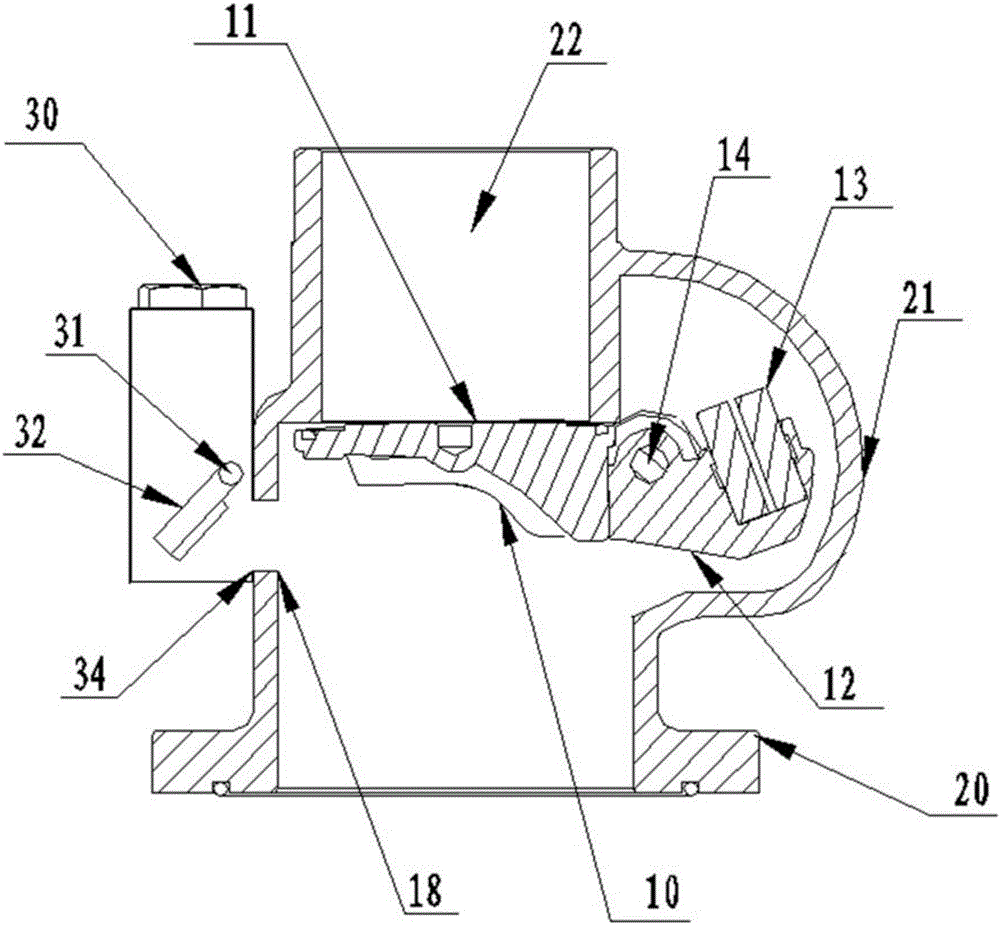
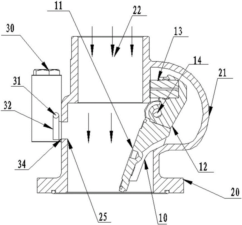
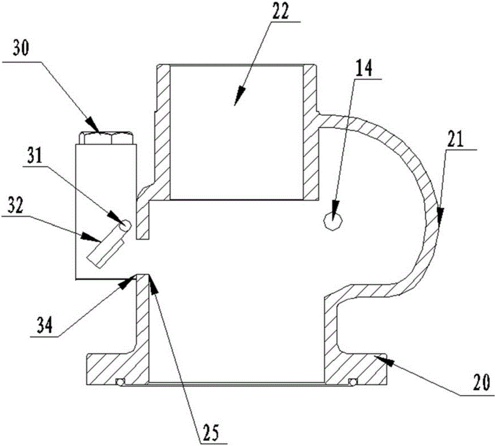
[0045] In a first embodiment of the invention, an intake valve is provided. Such as Figure 1~4 As shown, the air compressor of this embodiment includes a motor, a compressor host, an intake valve, a frequency converter, and a controller.

[0046] The intake valve includes: a check cover 10 , a valve body 20 , and a vent valve 30 .

[0047] The inside of the valve body 20 forms a first chamber, a valve body inlet 22 is formed above the first chamber, and a valve body pressure relief port 25 is formed on the side of the chamber. The valve body wall on the side where the first bolt 14 is located protrudes outwards to form a protruding chamber 21 . Wherein, the protruding chamber 21 provides space for the gravity block 13 fixed on the second end of the lever 12 to swing up and down.

[0048] The non-return cover includes: a cover body 11 , a lever 12 and a gravity block 13 . A first round hole 15 is opened on the lever 12, and the first bolt 14 passes through the first round ...

no. 3 example

[0056] In a first embodiment of the present invention, another intake valve is provided. The compressor of this embodiment is similar to the air compressor of the first embodiment, the only difference is that the present invention adopts tension spring tension to replace the self-weight effect of the non-return cover 10 and the isolating device 32 .

[0057] Specifically, as Figure 5-8 As shown, the intake valve in this embodiment includes: a check cover 10 , a valve body 20 , and a vent valve 30 .

[0058] The non-return cover (10) includes: a cover body 11, a first tension spring 17, and a first bolt 14. The cover body 11 is sheet-shaped, and has a third round hole 16 at one end. The first bolt 14 passes through the third round hole 16 and is fixed on the inner wall of the valve body 20 , which can completely fasten the air inlet 22 of the valve body. One end of the first extension spring 17 is fixed on the side of the cover body 11 close to the air inlet 22 of the valve ...


PUM


Abstract

The invention relates to the field of air compressors, and provides an air inlet valve and an air compressor applying the same. The air inlet valve comprises a check cover, a valve body and an air release valve; a first cavity is formed in the valve body, an air inlet of the valve body is formed over the first cavity, and a pressure relief opening is formed in the side face of the first cavity; the check cover is fixed in the portion, close to the air inlet of the valve body, of the first cavity through a first bolt and can rotate by taking the first bolt as a fulcrum; the air release valve is installed on the portion, close to the air inlet of the valve body, of the wall of the valve body, and an air inlet of the air release valve is communicated with the pressure relief opening of the valve body. According to the air inlet valve, a straight-through type air inlet channel is adopted, no hindering accessory exists in the channel, no electromagnetic valve is arranged, the compressor does not have the no-load process, therefore, the air inlet efficiency of the compressor is high, more energy is saved, and no electromagnetic valve damage risk is generated.

Description

technical field [0001] The invention relates to the field of air compressors, in particular to an intake valve and an air compressor using the same. Background technique [0002] Air compressors (referred to as air compressors) are widely used in various fields of industrial production. It is a general mechanical device, mainly used to provide compressed air for various pneumatic tools and air control instruments. [0003] At present, the internal structure of the intake valve used by the air compressor is complex, and the air will encounter greater resistance when passing through the check cover of the intake valve, which reduces the efficiency of air entering the compressor. In addition, when the pressure reaches the unloading pressure, the solenoid valve operates to control the vent valve to relieve the pressure, and the compressor enters the no-load state, causing damage to the solenoid valve and energy loss. [0004] In continuous production practice, the applicant fou...

Claims


Application Information

Patent Timeline
IPC IPC(8): F04B39/10F04B49/06
CPCF04B39/10F04B49/06
Inventor 潘晓峰徐刚
Owner 德哈哈压缩机江苏有限公司
Why Eureka
Try Eureka