Control device for hybrid vehicle

a control device and hybrid technology, applied in the direction of dynamo-electric converter control, instruments, transportation and packaging, etc., can solve the problems of reducing intake resistance, reduce electric power consumption, reduce the rotation speed of the motor generator, the effect of reducing the intake resistan

Active Publication Date: 2014-09-11
MITSUBISHI MOTORS CORP
View PDF3 Cites 6 Cited by
  • Summary
  • Abstract
  • Description
  • Claims
  • Application Information

AI Technical Summary

Benefits of technology

[0009]The present invention is achieved to solve the problem described above, and has an object to provide a control device for a hybrid vehicle that can reduce electric power consumption due to motoring performed in failure determination while ensuring accuracy of the failure determination.
[0011]Thus, when the motoring is performed in the failure determination of the detection unit by the failure determination unit, the throttle valve is forcedly opened, thereby reducing intake resistance. This can reduce a rotation speed of the motor generator in the motoring while ensuring an exhaust flow rate required for the failure determination, and reduce electric power consumption by the motor generator in the failure determination of the detection unit.

Problems solved by technology

Thus, when the motoring is performed in the failure determination of the detection unit by the failure determination unit, the throttle valve is forcedly opened, thereby reducing intake resistance.

Method used


Image

  • Control device for hybrid vehicle
  • Control device for hybrid vehicle
  • Control device for hybrid vehicle

Examples


Embodiment Construction

[0016]Now, an embodiment of the present invention will be described with reference to the drawings.

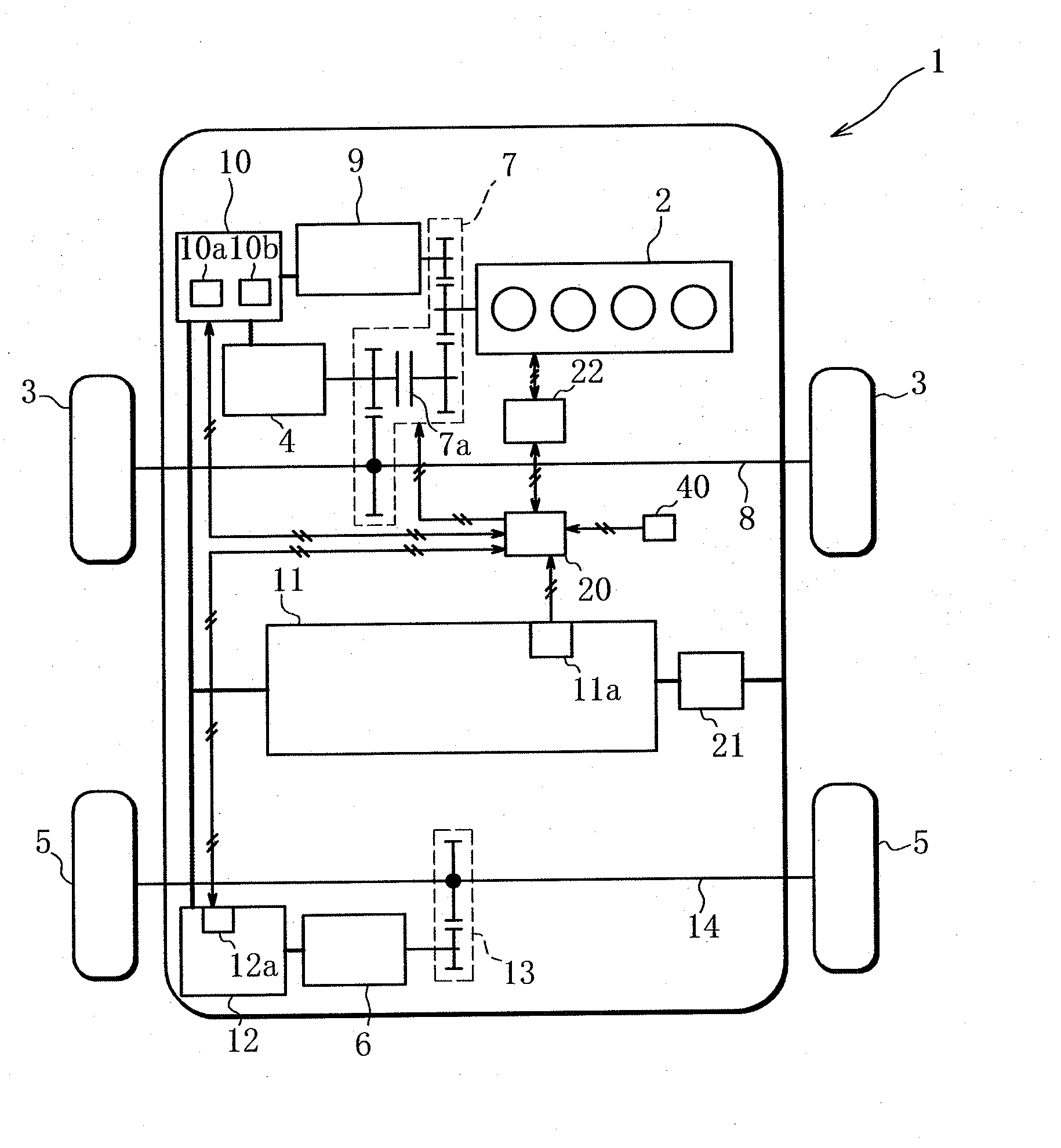
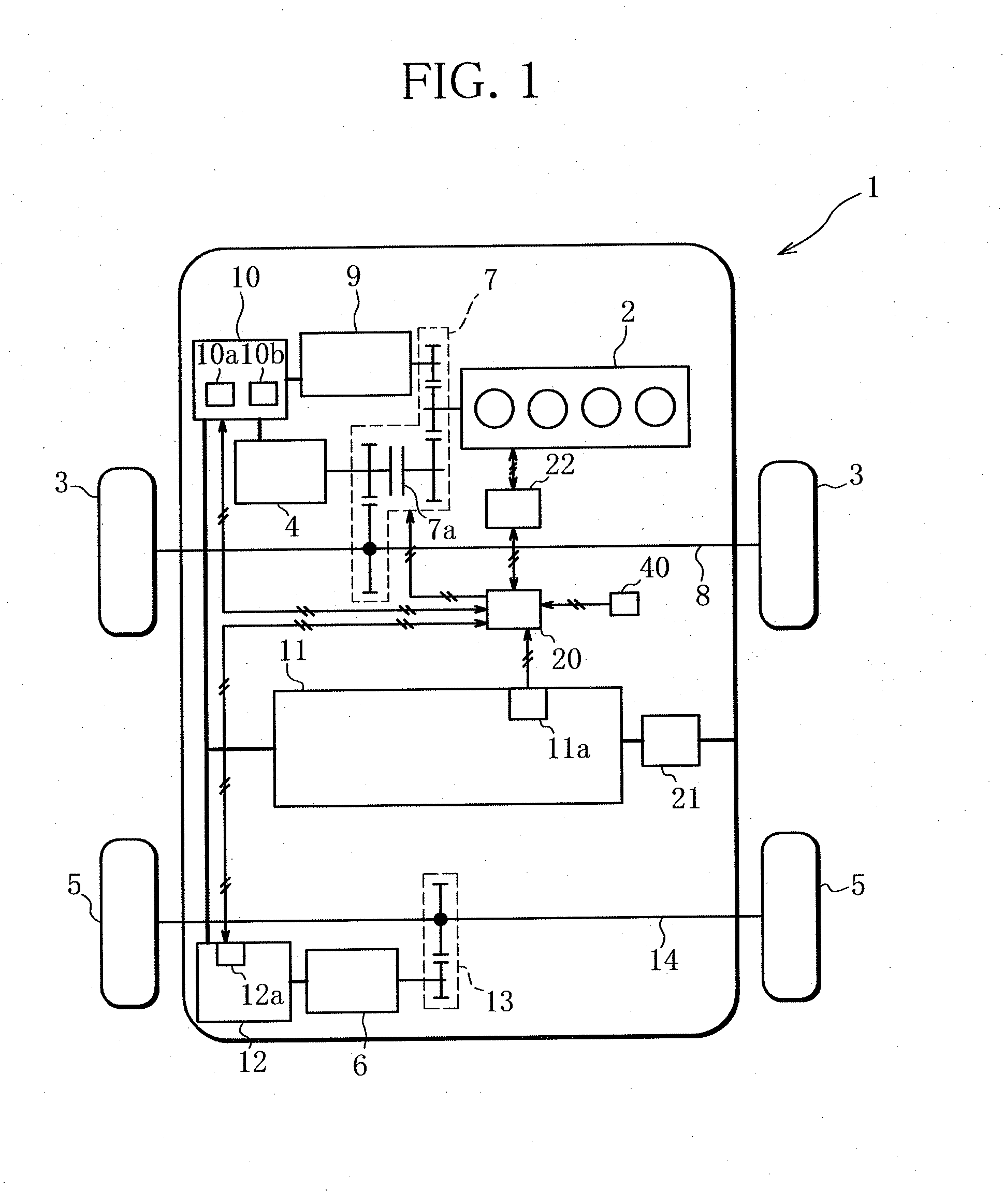
[0017]FIG. 1 is a schematic configuration diagram of a plug-in hybrid vehicle (hereinafter referred to as vehicle 1) according to an embodiment of the present invention.

[0018]The vehicle 1 of this embodiment is a four-wheel-drive vehicle that can travel by driving front wheels 3 using an output of an engine 2, and includes an electric front motor 4 (driving motor) that drives the front wheels 3, and an electric rear motor 6 (driving motor) that drives rear wheels 5.

[0019]The engine 2 can drive a drive axle 8 of the front wheels 3 via a reducer 7, and drive a motor generator 9 via the reducer 7 to generate electric power.

[0020]The front motor 4 is driven by electric power of a high voltage supplied from a driving battery 11 and the motor generator 9 included in the vehicle 1 via a front inverter 10 to drive the drive axle 8 of the front wheels 3 via the reducer 7. The reducer 7 includes...


PUM


Abstract

In a hybrid vehicle that selects a series mode in which an engine drives a motor generator to generate electric power and a driving motor drives drive wheels, fuel supply to the engine is stopped and motoring in which the motor generator forcedly drives the engine can be performed, failure determination of a front O2 sensor and a rear O2 sensor provided in an exhaust passage of the engine can be performed based on a change in a detection value of the sensors when the fuel supply is stopped, and a throttle valve of the engine is forcedly opened in the motoring.

Description

BACKGROUND OF THE INVENTION[0001]1. Field of the Invention[0002]The present invention relates to a technique of reducing electric power consumption in failure determination of a detection unit provided in an exhaust system of an engine of a hybrid vehicle.[0003]2. Description of the Related Art[0004]Among recently developed hybrid vehicles, a vehicle has been developed that allows a travel mode (series mode) in which an engine drives a motor generator to generate electric power and only an electric motor drives travel driving wheels.[0005]Further, for the hybrid vehicle that allows the travel mode, a technique has been developed of performing failure determination of a detection unit (air-fuel ratio sensor, oxygen concentration sensor, catalyst monitor, or the like) in an exhaust system of an engine in the travel mode.[0006]For example, Japanese Patent Laid-Open No. 2011-194976 discloses a technique of stopping fuel supply to an engine and performing so-called motoring in which a mo...

Claims


Application Information

Patent Timeline
Patent Type & Authority Applications(United States)
IPC IPC(8): G01M15/02H02P1/00H02K99/00B60L50/16
CPCG01M15/02H02P1/00H02K57/003B60Y2300/47B60K6/442B60W10/06B60W10/08B60W2710/0605B60Y2300/64B60W20/50Y02T10/62Y02T10/64Y02T10/7072
Inventor MATSUNAGA, HIDEOIKEDAYA, HISAKAZUKAMURA, HITOSHIMIYATA, TOSHIYUKI
Owner MITSUBISHI MOTORS CORP
Why Eureka
Try Eureka