Supercharge Your Innovation With Domain-Expert AI Agents!

Harmonic tooth difference transmission device

A technology of speed change device and tooth difference, applied in the direction of transmission device, belt/chain/gear, mechanical equipment, etc., can solve problems such as inability to implement application

Active Publication Date: 2019-01-11
国际精工股份有限公司
View PDF6 Cites 0 Cited by
  • Summary
  • Abstract
  • Description
  • Claims
  • Application Information

AI Technical Summary

Problems solved by technology

However, the reduction ratio design of the existing harmonic reduction device is only suitable for the speed ratio in the range of 1:30 to 1:320. If the speed ratio is too large or too small, the application cannot be implemented.
[0003] In view of the technical problem that the above-mentioned harmonic transmission device can only be applied to a single section reduction ratio, the inventor deeply feels that there is still room for improvement

Method used


Image

  • Harmonic tooth difference transmission device
  • Harmonic tooth difference transmission device
  • Harmonic tooth difference transmission device

Examples


Embodiment Construction

[0025] The present invention will be further described below in conjunction with specific examples, so that those skilled in the art can better understand the present invention and implement it, but the given examples are not intended to limit the present invention.

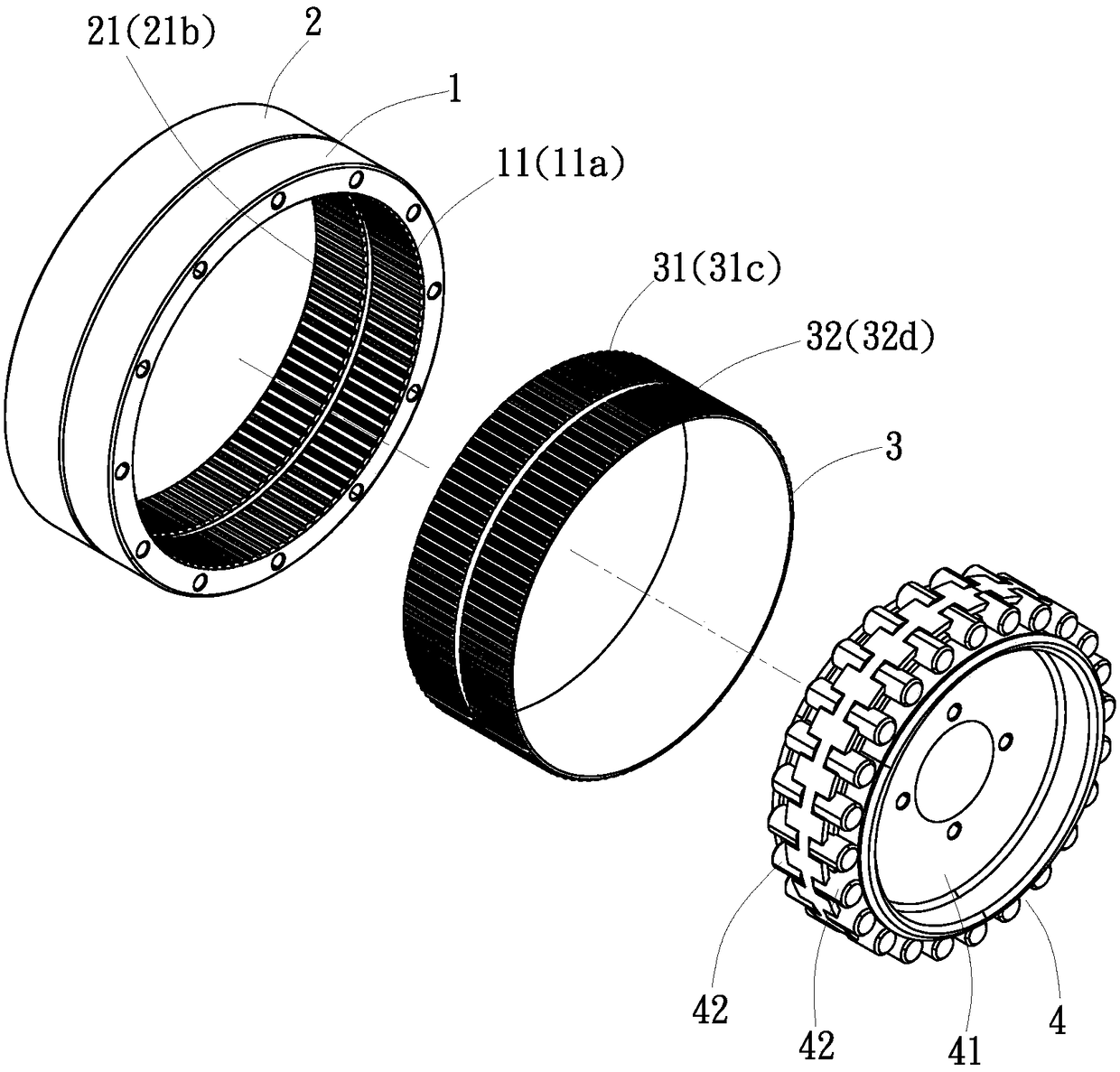
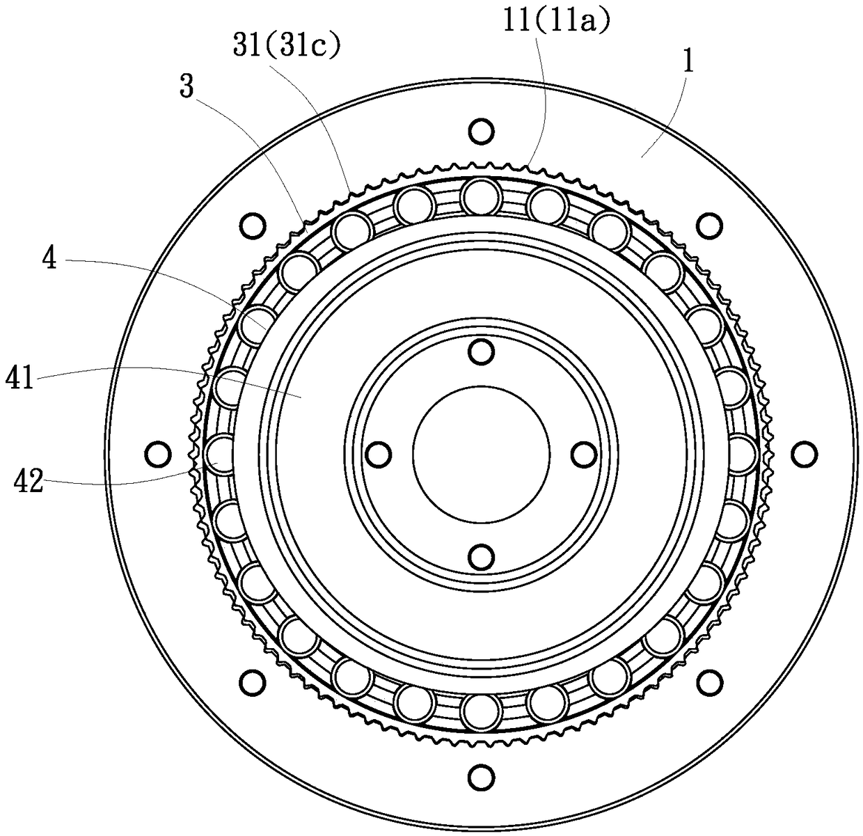
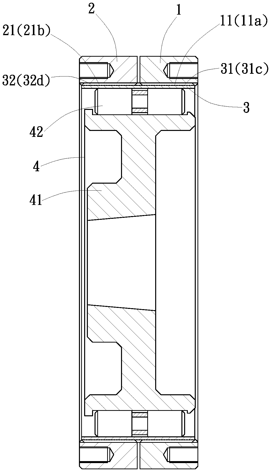
[0026] refer to figure 1 , figure 2 and image 3 As shown, the harmonic tooth difference transmission device of the present invention is used to connect to the mechanical power output source, and then achieve the rotational speed of the adjusted power. Its preferred embodiment includes: a first inner gear ring 1, which is implemented as a perfect circle The ring body has a first internal tooth 11 on an inner ring surface thereof, and the first internal tooth 11 has a tooth number 11a. A second internal gear ring 2, which is implemented as a perfect torus, is coaxially aligned on one side of the first internal gear ring 1, and has a second internal tooth 21 on an internal ring surface, and the second internal t...


PUM


Abstract

The invention discloses a harmonic tooth-difference speed transmission. The harmonic tooth-difference speed transmission comprises a first inner tooth ring and a second inner tooth ring which are coaxially parallel to each other, and an outer tooth ring as well as a harmonic generator arranged in the outer tooth ring; first inner teeth are arranged on the inner ring surface of the first inner tooth ring; second inner teeth are arranged on the inner ring surface of the second inner tooth ring; the outer tooth ring is coaxially arranged in the first inner tooth ring and the second inner tooth ring, and is provided with first outer teeth and second outer teeth which correspond to the first inner teeth and the second inner teeth; and especially, tooth number of the first outer teeth is smaller than that of the first inner teeth and that of the second inner teeth; tooth number of the second outer teeth is not greater than that of the first inner teeth and that of the second inner teeth; and tooth number of the first outer teeth is same with or different from that of the second outer teeth. The harmonic tooth-difference speed transmission disclosed by the invention can be applied in states such as reduction, acceleration or speed regulation.

Description

technical field [0001] The present invention relates to a tooth difference transmission device, especially a harmonic tooth difference in which an external gear ring with two rows of external teeth is arranged in two parallel internal gear rings, and power is input or output through a harmonic generator. transmission. Background technique [0002] The existing harmonic deceleration device is a transmission device with a high reduction ratio, such as the harmonic drive transmission disclosed in U.S. Patent No. 2906143. In the cup-shaped or ring-shaped flexible gear, after the cam is operated by the transmission force, the two ends of the long axis of the cam surface can stretch the flexible gear, so that the flexible gear can be matched with the set A circular rigid internal-toothed spline produces a tight meshing state without gaps, and a deceleration transmission effect is produced by the designed tooth number difference between the flexible gear and the internal-toothed s...

Claims


Application Information

Patent Timeline
Patent Type & Authority Patents(China)
IPC IPC(8): F16H49/00
CPCF16H49/001
Inventor 李茂碷
Owner 国际精工股份有限公司
Features
  • R&D
  • Intellectual Property
  • Life Sciences
  • Materials
  • Tech Scout
  • Unparalleled Data Quality
  • Higher Quality Content
  • 60% Fewer Hallucinations
Learn More