Power converting device

a power conversion and power technology, applied in the direction of dc-ac conversion without reversal, dc-ac circuit to reduce harmonics/ripples, transportation and packaging, etc., can solve the problem of difficult manufacturing of an active filter system in a compact structure, and achieve the effect of small size and high precision

Active Publication Date: 2009-02-03
MITSUBISHI ELECTRIC CORP
View PDF14 Cites 142 Cited by
  • Summary
  • Abstract
  • Description
  • Claims
  • Application Information

AI Technical Summary

Benefits of technology

[0067]The line current Is is controlled by varying the inverter current Ia by performing the aforementioned gradational output voltage control of the single-phase multiplex inverter 3 in the second embodiment as well. Consequently, the single-phase multiplex inverter 3 of the second embodiment controls the inverter current Ia to follow the harmonic compensation reference current 24a to cancel out harmonic currents contained in the load current as in the foregoing first embodiment. The second embodiment of the invention therefore produces the same advantageous effects as the first embodiment.
[0068]While the foregoing embodiments are concerned with the power converting devices used as the active filters, a power converting device of a third embodiment described below is used as a system interconnection inverter for converting DC power fed from a DC power source into AC power and thereby connecting the DC power source to a power system. FIG. 13 is a circuit diagram showing the configuration of the power converting device according to the third

Problems solved by technology

As the conventional active filter employs the high-frequency PWM inverter as mentioned above, the active filter has needed a large-scale filter circuit for suppressing leakage of harmonic currents to the power supply side, making it difficult to manufacture an active filter system in a compact structure.

Method used


Image

  • Power converting device
  • Power converting device
  • Power converting device

Examples


first embodiment

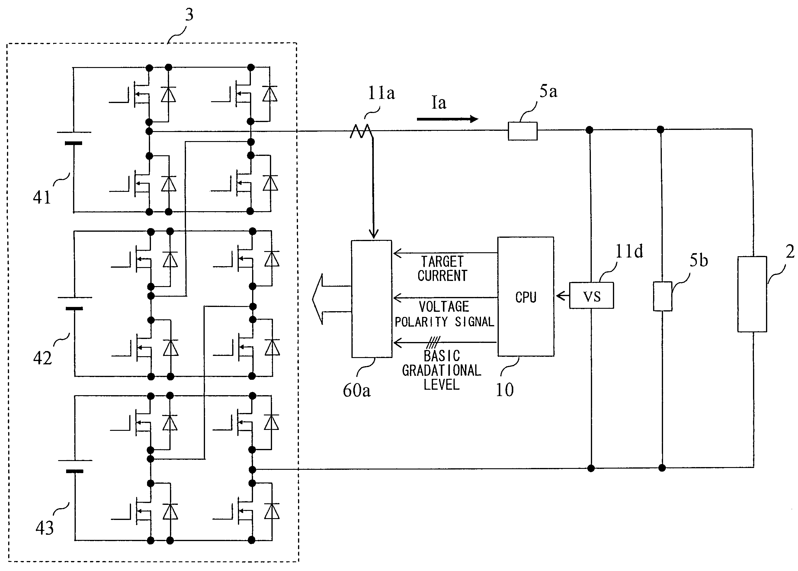
[0026]FIG. 1 is a block diagram showing the configuration of a main part of a power converting device according to a first embodiment of the invention connected between a single-phase power supply 1 and a single-phase load 2 in parallel therewith, the power converting device being used as an active filter.

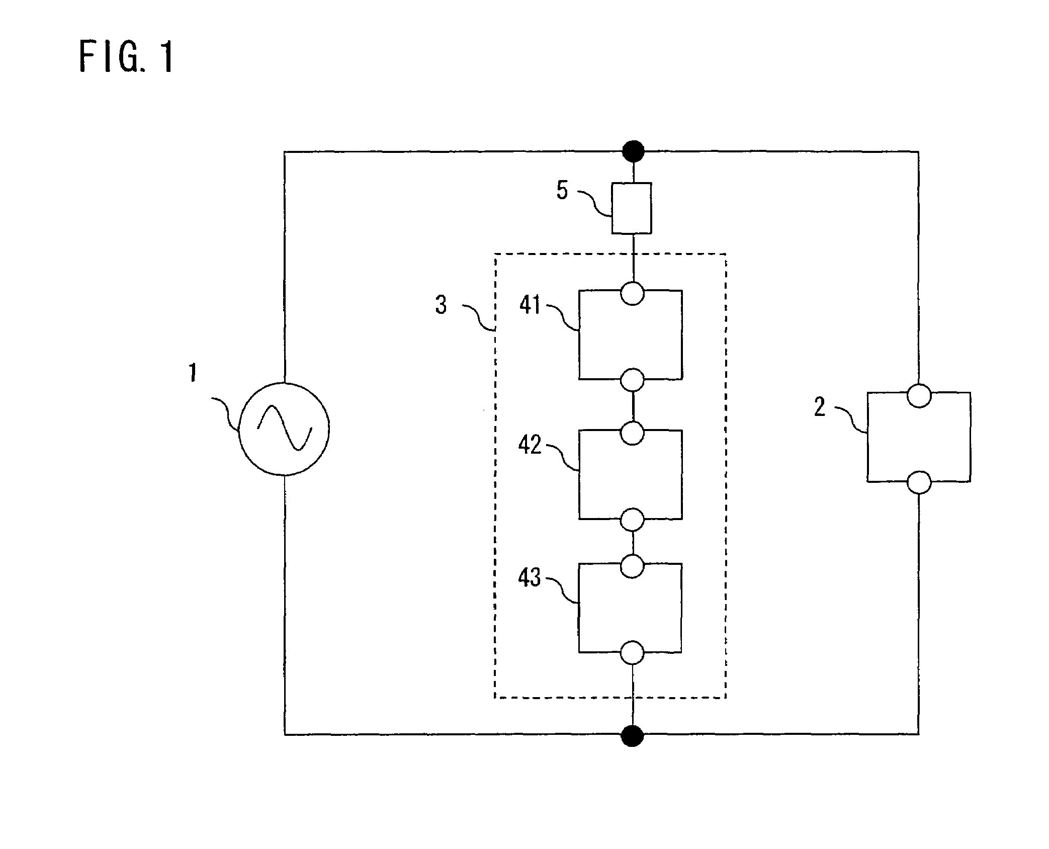
[0027]As shown in FIG. 1, the power converting device of the embodiment includes a single-phase multiplex converter, or a single-phase multiplex inverter 3, in which a plurality of (three in this embodiment) single-phase inverters 41-43 are connected in series. The single-phase multiplex inverter 3 is series-connected to a filter circuit 5 made up of a line reactor, and the single-phase multiplex inverter 3 and the line reactor are together connected to the single-phase power supply 1 in parallel therewith.

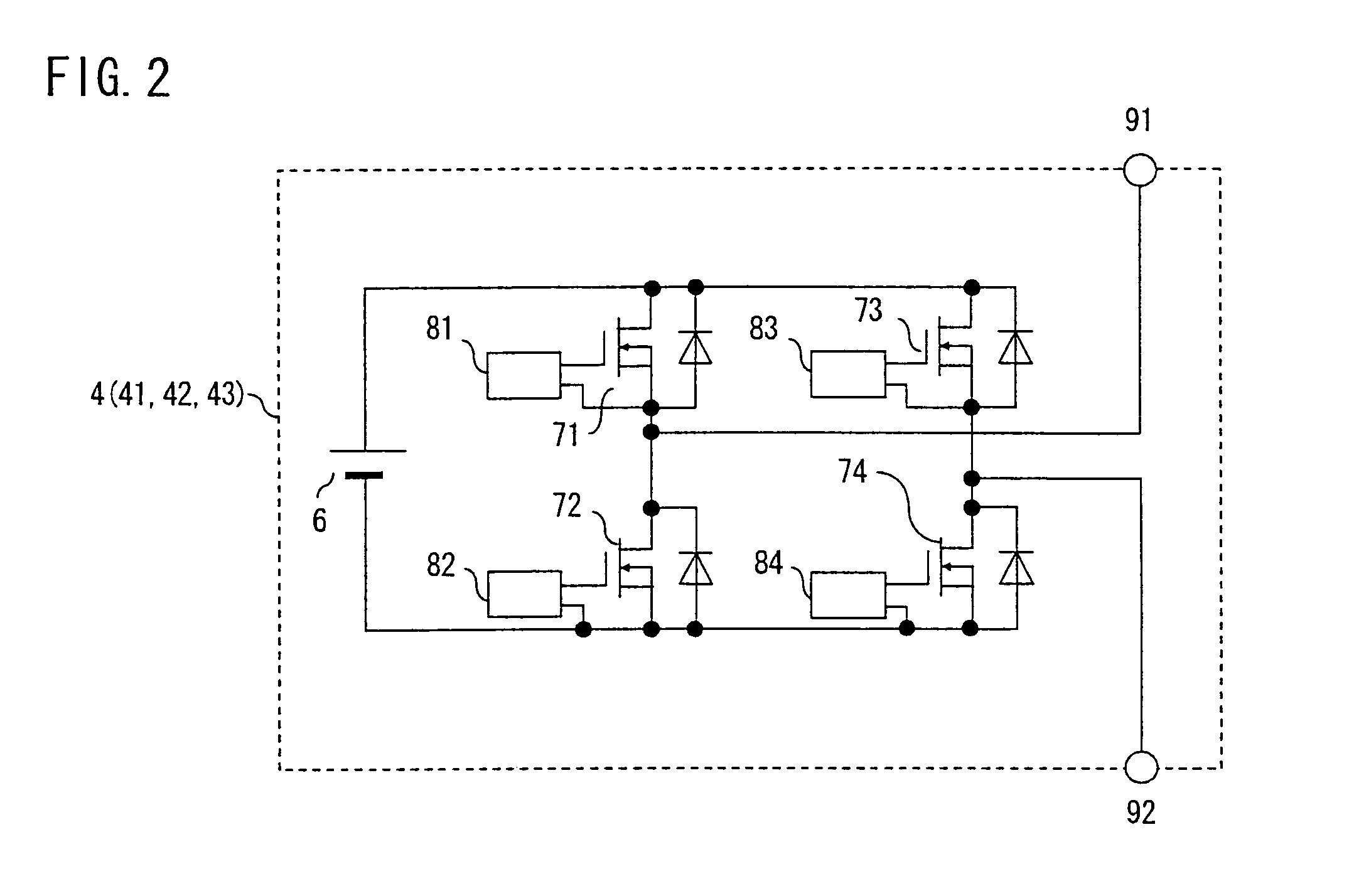
[0028]FIG. 2 is a circuit diagram showing the configuration of each of the single-phase inverters 41-43 (hereinafter referred to collectively as the single-phase inverters 4) con...

second embodiment

[0065]While the single-phase multiplex inverter 3 is controlled in such a manner that the inverter current Ia follows the harmonic compensation reference current 24a in the foregoing first embodiment, the embodiment may be so modified as to control the single-phase multiplex inverter 3 such that the line current Is follows a reference current (load current fundamental component value) obtained by smoothing the discrete load current fundamental component value output from-the CPU 10 by the filter 23 as shown in FIG. 12.

[0066]Also, while the load current IL is passed through the bandpass filter 13 to remove the harmonic components contained therein and extract the fundamental component which is input into the CPU 10 in the first embodiment, the fundamental component of the load current IL is extracted by the CPU 10 in this modified form of the first embodiment, or a second embodiment of the invention.

[0067]The line current Is is controlled by varying the inverter current Ia by perform...

third embodiment

[0068]While the foregoing embodiments are concerned with the power converting devices used as the active filters, a power converting device of a third embodiment described below is used as a system interconnection inverter for converting DC power fed from a DC power source into AC power and thereby connecting the DC power source to a power system. FIG. 13 is a circuit diagram showing the configuration of the power converting device according to the third embodiment of the invention.

[0069]Like the power converting device of the first embodiment, the power converting device of the third embodiment is a single-phase multiplex converter, or a single-phase multiplex inverter 3, in which a plurality of (three in this embodiment) single-phase inverters 41-43 are connected in series. The single-phase multiplex inverter 3 is connected to a load 2 (which is a power system in this embodiment) via a reactor 5a. A capacitor 5b parallel-connected to the load 2 serves as a filter for removing harm...


PUM


Abstract

A power converting device includes a single-phase multiplex converter used as an active filter and a control device. The single-phase multiplex converter includes multiple single-phase inverters connected in series at AC output sides. Each of the single-phase inverters converts DC power fed from a DC power supply into AC power. The control device includes hysteresis comparators and controls output voltage of the single-phase multiplex converter by gradational output voltage control, based on the sum of selectively combined output voltages of the multiple single-phase inverters. The control device controls the single-phase multiplex converter so that an output current follows a harmonic compensation reference current, canceling harmonics leaking from a load to which the power converting device is connected.

Description

BACKGROUND OF THE INVENTION[0001]1. Field of the Invention[0002]The present invention relates to a power converting device capable of controlling an output current. More particularly, the invention pertains to an active filter for suppressing harmonic current components which leak out of a load apparatus and flow to power supply side by injecting a harmonic compensation current for canceling the harmonic current components.[0003]2. Description of the Background Art[0004]An active filter is a device which generates a harmonic compensation current for suppressing harmonic currents produced by a load apparatus. Connected to a power supply line of the load apparatus at a point close thereto, the active filter injects the harmonic compensation current into the power supply line to cancel the harmonic currents leaking out of the load apparatus. A conventional active filter detects a load current, separates the load current into a fundamental component and harmonic components thereof, extr...

Claims


Application Information

Patent Timeline
Patent Type & Authority Patents(United States)
IPC IPC(8): H02J1/00
CPCH02M7/49
Inventor MORI, OSAMUYAMADA, MASAKIIWATA, AKIHIKO
Owner MITSUBISHI ELECTRIC CORP
Why Eureka
Try Eureka