Composite right/left handed (CRLH) couplers

a right/left-handed, coupler technology, applied in the direction of coupling devices, electrical equipment, transmission, etc., can solve the problem that conventional coupled-line couplers cannot achieve tight coupling levels, and achieve the effect of enhancing bandwidth, reducing device size, and increasing bandwidth

Active Publication Date: 2005-11-17
RGT UNIV OF CALIFORNIA
View PDF0 Cites 142 Cited by
  • Summary
  • Abstract
  • Description
  • Claims
  • Application Information

AI Technical Summary

Benefits of technology

[0043] Another aspect of the invention is to provide a compact enhanced-bandwidth hybrid ring coupler whic

Problems solved by technology

This coupler can achieve arbitrary coupling levels (i.e., up to −0.5 dB) despite a relatively wide gap between the two TLs (typically

Method used


Image

  • Composite right/left handed (CRLH) couplers
  • Composite right/left handed (CRLH) couplers
  • Composite right/left handed (CRLH) couplers

Examples


Embodiment Construction

[0084] Referring more specifically to the drawings, for illustrative purposes the present invention is embodied in the apparatus generally shown in FIG. 1 through FIG. 21. It will be appreciated that the apparatus may vary as to configuration and as to details of the parts, and that the method may vary as to the specific steps and sequence, without departing from the basic concepts as disclosed herein.

[0085] 1. Introduction to Coupler Embodiments.

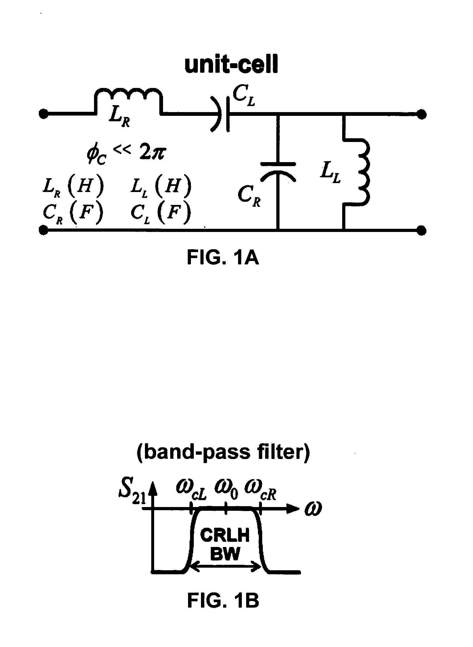
[0086]FIG. 1A and FIG. 1B illustrate the general characteristics of an artificial CRLH-TL. FIG. 1A depicts a unit cell of the CRLH-TL while FIG. 1B illustrates general bandpass filter characteristics. The pure RH-TL (low-pass) and LH-TL (high-pass) are respectively obtained by suppressing the elements of the opposite type. An essential requirement for the artificial CRLH-TL to mimic an ideal CRLH-TL (in its transmission-band) is that the electrical length of the unit cell be small, practically smaller than approximately π / 2. Under this co...


PUM


Abstract

High-frequency couplers and coupling techniques are described utilizing artificial composite right/left-handed transmission line (CRLH-TL). Three specific forms of couplers are described; (1) a coupled-line backward coupler is described with arbitrary tight/loose coupling and broad bandwidth; (2) a compact enhanced-bandwidth hybrid ring coupler is described with increased bandwidth and decreased size; and (3) a dual-band branch-line coupler that is not limited to a harmonic relation between the bands. These variations are preferably implemented in a microstrip fabrication process and may use lumped-element components. The couplers and coupling techniques are directed at increasing the utility while decreasing the size of high-frequency couplers, and are suitable for use with separate coupler or couplers integrated within integrated devices.

Description

CROSS-REFERENCE TO RELATED APPLICATIONS [0001] This application claims priority from U.S. provisional application Ser. No. 60 / 556,981 filed on Mar. 26, 2004, incorporated herein by reference in its entirety.STATEMENT REGARDING FEDERALLY SPONSORED RESEARCH OR DEVELOPMENT [0002] This invention was made with Government support under Grant No. N00014-01- 0803, awarded by the Department of Defense ARO MURI. The Government has certain rights in this invention.INCORPORATION-BY-REFERENCE OF MATERIAL SUBMITTED ON A COMPACT DISC [0003] Not Applicable NOTICE OF MATERIAL SUBJECT TO COPYRIGHT PROTECTION [0004] A portion of the material in this patent document is subject to copyright protection under the copyright laws of the United States and of other countries. The owner of the copyright rights has no objection to the facsimile reproduction by anyone of the patent document or the patent disclosure, as it appears in the United States Patent and Trademark Office publicly available file or records...

Claims


Application Information

Patent Timeline
IPC IPC(8): H01P5/18
CPCH01P5/227
Inventor ITOH, TATSUOCALOZ, CHRISTOPHELIN, I-HSIANGOKABE, HIROSHI
Owner RGT UNIV OF CALIFORNIA
Why Eureka
Try Eureka