Rotating shaft sealing structure and sealing ring for rotating shaft seal

A shaft sealing and sealing ring technology, which is applied in the direction of engine sealing, engine components, mechanical equipment, etc., can solve the problems of not being able to meet the sealing protection level and effectively prevent harmful impurities, so as to improve the sealing protection level and meet the use requirements Effect

Active Publication Date: 2017-01-04
GREE ELECTRIC APPLIANCES INC
View PDF13 Cites 1 Cited by
  • Summary
  • Abstract
  • Description
  • Claims
  • Application Information

AI Technical Summary

Problems solved by technology

[0004] However, at present, the protection level of motors in most industrial applications is at or below IP54, and the overall protection performance of the motor must reach IP67 or above. The key lies in the protection of the dynamic seal at the shaft extension end, while the static seal at other positions is relatively easy to meet t

Method used


Image

  • Rotating shaft sealing structure and sealing ring for rotating shaft seal
  • Rotating shaft sealing structure and sealing ring for rotating shaft seal
  • Rotating shaft sealing structure and sealing ring for rotating shaft seal

Examples


Embodiment Construction

[0034] One of the cores of the present invention is to provide a sealing ring for rotating shaft sealing, in order to achieve a higher level of sealing at the protruding position of the rotating shaft.

[0035] Another core of the present invention is to provide a rotating shaft sealing structure using the above-mentioned sealing ring.

[0036] In order to enable those skilled in the art to better understand the solution of the present invention, the present invention will be further described in detail below in conjunction with the accompanying drawings and specific embodiments.

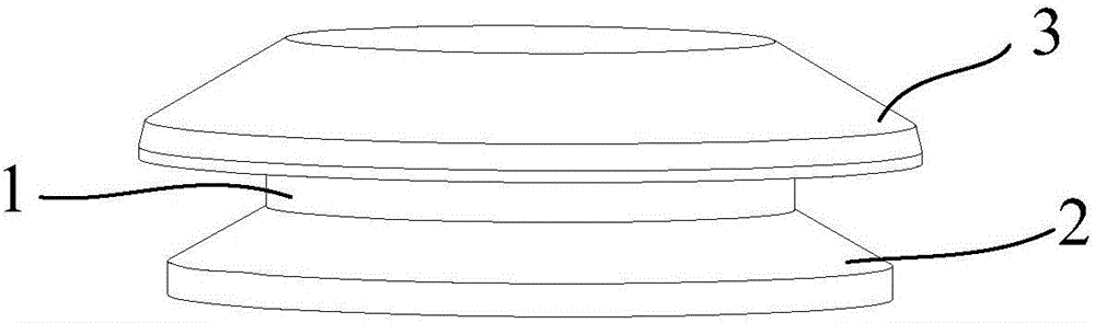
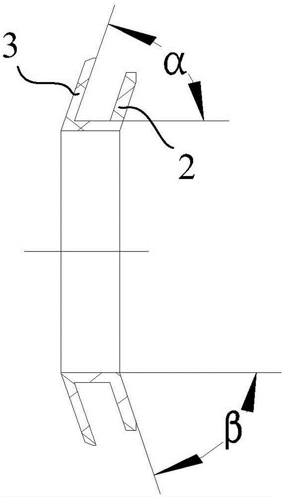
[0037] Please refer to figure 1 and figure 2 , figure 1 It is a schematic diagram of the overall structure of the sealing ring for rotating shaft sealing disclosed in the embodiment of the present invention, figure 2 for figure 1 The cross-sectional schematic diagram of the seal ring for the shaft seal shown in .

[0038] The sealing ring for rotating shaft sealing disclosed in the present in...


PUM


Abstract

The invention relates to a sealing ring for rotating shaft seal. The sealing ring is used for being mounted on a rotating shaft and embedded into a sealing ring groove of a shell, and comprises a rubber main body, wherein a sleeving hole through which the rotating shaft is in interference fit is formed in the center of the rubber main body; the root is connected with the rubber main body; a first circular sealing lip and a second circular sealing lip are arranged along the axial direction of the rubber main body at an interval; an included angle between a lip surface of each of the first circular sealing lip and the second circular sealing lip and the axis of the rubber main body is an acute angle; an outer edge of the first circular sealing lip is a first sealing part in squeeze fit with the groove bottom of the sealing ring groove; and an outer edge of the second circular sealing lip is a second sealing part in squeeze fit with the side wall of the sealing ring groove. According to the sealing ring for rotating shaft seal, the sealing property of a shaft extension position can be effectively improved. The invention also relates to a shaft sealing structure adopting the sealing ring for shaft seal.

Description

technical field [0001] The invention relates to the technical field of rotating component sealing, in particular to a rotating shaft sealing structure and a sealing ring for rotating shaft sealing. Background technique [0002] Some power equipment for industrial applications or power equipment used outdoors generally have higher requirements on the waterproof and dustproof performance of these power equipment because they are in a relatively harsh working environment. [0003] Taking the electric motor as an example, when an electric vehicle drives in a rainy day, or the electric vehicle drives through a low-lying waterlogged place, its drive motor may be soaked in water for a short time. Therefore, in order to ensure the safety of the drive motor, the protection level of the motor is required to be above IP67 . [0004] However, at present, the protection level of motors in most industrial applications is IP54 or below, and the overall protection performance of the motor ...

Claims


Application Information

Patent Timeline
IPC IPC(8): F16J15/3232
CPCF16J15/3232
Inventor 张玉尹相宇肖智峰
Owner GREE ELECTRIC APPLIANCES INC
Why Eureka
Try Eureka