
Test unit positioning mechanism of test device and test equipment for its application

A technology of testing unit and positioning mechanism, which is applied in the direction of the measuring device casing, etc., which can solve problems such as time-consuming work, inability to improve production efficiency, and limited space

Active Publication Date: 2021-01-29
HON PRECISION INC
View PDF7 Cites 0 Cited by
  • Summary
  • Abstract
  • Description
  • Claims
  • Application Information

AI Technical Summary

Problems solved by technology

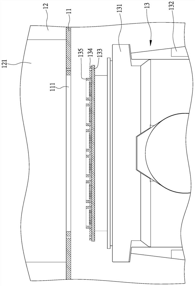
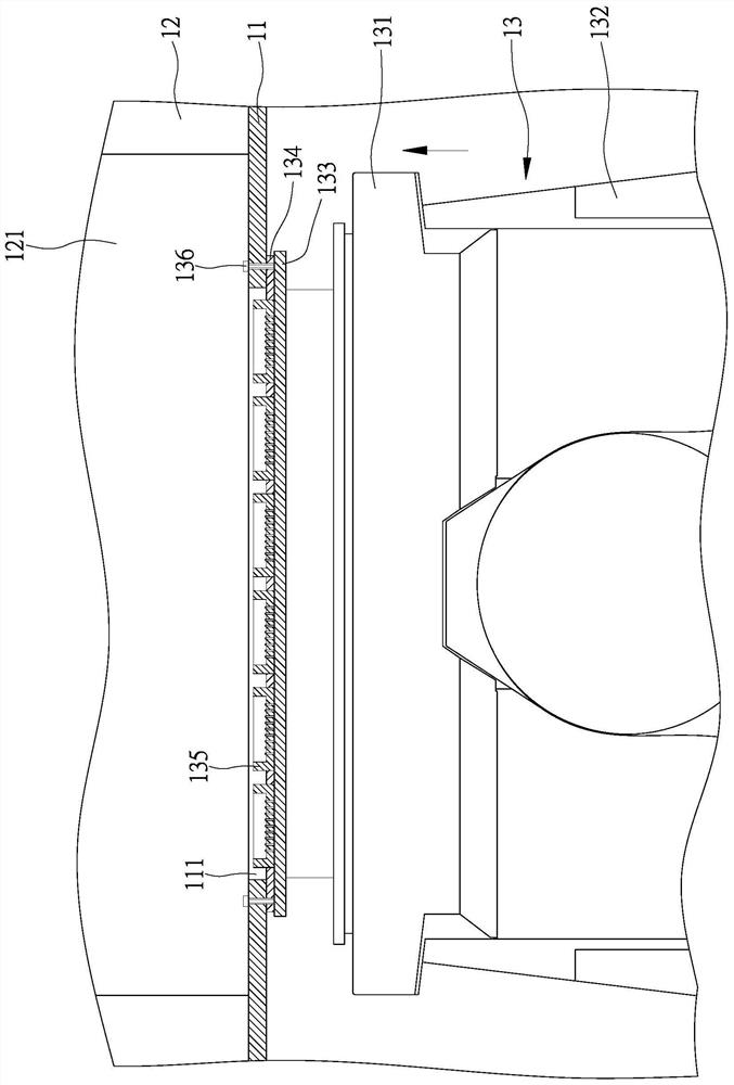
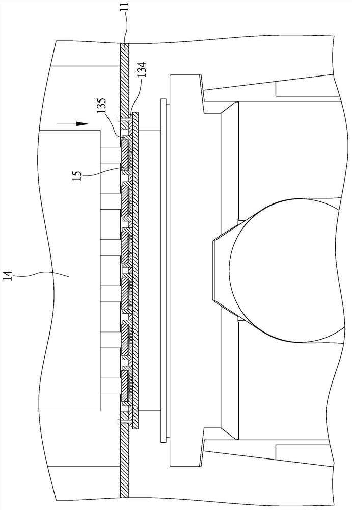
[0003] 1. Since the base plate 134 of the test unit is locked on the tester 131, and the tester 131 is assembled under the machine table 11, there is no space under the machine table 11 for the staff to carry out the operation of locking the base board 134, so that The staff must perform the operation of locking the substrate 134 from the entrance and exit 121 of the outer cover 12, but the interior of the outer cover 12 is also equipped with other devices, so that the space is limited, which makes it quite inconvenient for the staff to perform the operation of locking the substrate 134 in a narrow space.
[0004] 2. When replacing the test seat 135 of the test unit, the staff must shut down the test equipment, and then dismantle the plurality of anchors 136 on the machine table 11 one by one, so as to remove the base plate 134 of the test unit and fix the new test unit When using multiple anchors 134 to fix the new substrate lock on the machine 11, the entire test equipment must wait for repeated assembly and disassembly of the plurality of anchors 136 before it can be turned on to perform the test operation, which is not only labor-intensive time, can not improve production efficiency

Method used


Image

  • Test unit positioning mechanism of test device and test equipment for its application
  • Test unit positioning mechanism of test device and test equipment for its application
  • Test unit positioning mechanism of test device and test equipment for its application

Examples


Embodiment Construction

[0047] In order to make your examiner further understand the present invention, hereby give a preferred embodiment and cooperate with the drawings, as follows in detail:

[0048] see Figure 5 , Image 6 The positioning mechanism 20 of the test device of the present invention includes at least one power source and at least one abutting member, and the at least one power source is used to drive at least one abutting member for displacement in at least one direction, and the power source can be installed on the machine table Bottom surface or independent plate body, in this embodiment, positioning mechanism 20 is provided with a fixed plate 21 with accommodating space 211, and this fixed plate 21 is equipped with a plurality of power sources that can be press cylinders 22, and a plurality of press cylinders 22 Arranged in the first and second directions respectively; at least one push-off member 23 is provided with at least one push-off component 231, and the push-off component...


PUM


Abstract

The present invention provides a test unit positioning mechanism of test equipment and test equipment provided with the test unit positioning mechanism. The bottom surface of the machine table of the test equipment is provided with a positioning mechanism. The positioning mechanism comprises a fixing plate provided with an accommodating space. At least one power source is arranged on the fixing plate. The power source drives at least one abutting member to move in at least one direction. A test unit comprises a carrier provided with a test bench. The test mechanism of the test unit drives the carrier to move into the accommodating space of the fixing plate. The positioning mechanism is driven by the power source to drive the abutting member to move, so that the carrier is pushed to attach to the machine table. In this way, the test unit provided with the test bench is positioned. During the replacement of the test bench, the positioning mechanism is driven by the power source to drive the abutting member to be separated from the carrier, so that the test unit with the test bench can be removed. The test mechanism drives the test unit to get away from the machine table. Therefore, the test unit provided with the test bench is automatically positioned or removed by the positioning mechanism, so that the replacement operation time is saved. As a result, the usage convenience and the production efficiency are improved.

Description

technical field [0001] The invention relates to a positioning mechanism capable of automatically positioning or removing a test unit with a test seat, saving the working time of replacing the test seat, and improving the convenience of use and production efficiency. Background technique [0002] Nowadays, after the electronic components are manufactured, they are transported to testing equipment for testing operations to eliminate defective products. Please refer to Figures 1, 2, and 3. The testing equipment is provided with a machine table 11 with an opening 111. The top of the machine platform 11 is provided with an outer cover 12 with an entrance and exit 121, and a test device 13 for testing electronic components is arranged below the machine platform 11. The test device 13 is provided with a tester connected to a central control unit (not shown). 131, the tester 131 is displaced in the first and second directions (such as X and Y directions) by the transfer structure (n...

Claims


Application Information

Patent Timeline
Patent Type & Authority Patents(China)
IPC IPC(8): G01R1/04
Inventor 余俊宏
Owner HON PRECISION INC
Learn More