Check patentability & draft patents in minutes with Patsnap Eureka AI!

An electric valve interlock control system and control method

A control system and valve technology, applied in general control systems, control/regulation systems, electrical program control, etc., can solve problems such as electric valve damage, and achieve the effect of simple structure and strong practicability

Active Publication Date: 2019-04-30
天津市美络科技发展有限公司
View PDF6 Cites 0 Cited by
  • Summary
  • Abstract
  • Description
  • Claims
  • Application Information

AI Technical Summary

Problems solved by technology

[0002] With the continuous advancement of science and technology, electromechanical systems are widely used in production and life, and electric valves are widely used in electromechanical systems. In order to fully ensure the safety of users, the opening and closing of existing electric valves are usually operated by independent When two separate MOS tube channels are used to drive two independent coils, it should be ensured that only one of the two electromagnetic coils is powered on at the same time. If the two electromagnetic coils are powered on at the same time, it may cause damage to the electric valve. In order to prevent this from happening, software is usually used to make the output values ​​of the open electromagnetic coil and the close electromagnetic coil inconsistent, but this method is very easy to cause the open coil and the open coil of the dodge door to be damaged due to the carelessness of the programmer or the loopholes and errors of the software. Closing the coil while energizing causes damage to the electric valve

Method used


Image

  • An electric valve interlock control system and control method

Examples


Embodiment Construction

[0023] It should be noted that the embodiments of the present invention and the features of the embodiments may be combined with each other under the condition of no conflict.

[0024] The present invention will be described in detail below with reference to the accompanying drawings and in conjunction with the embodiments.

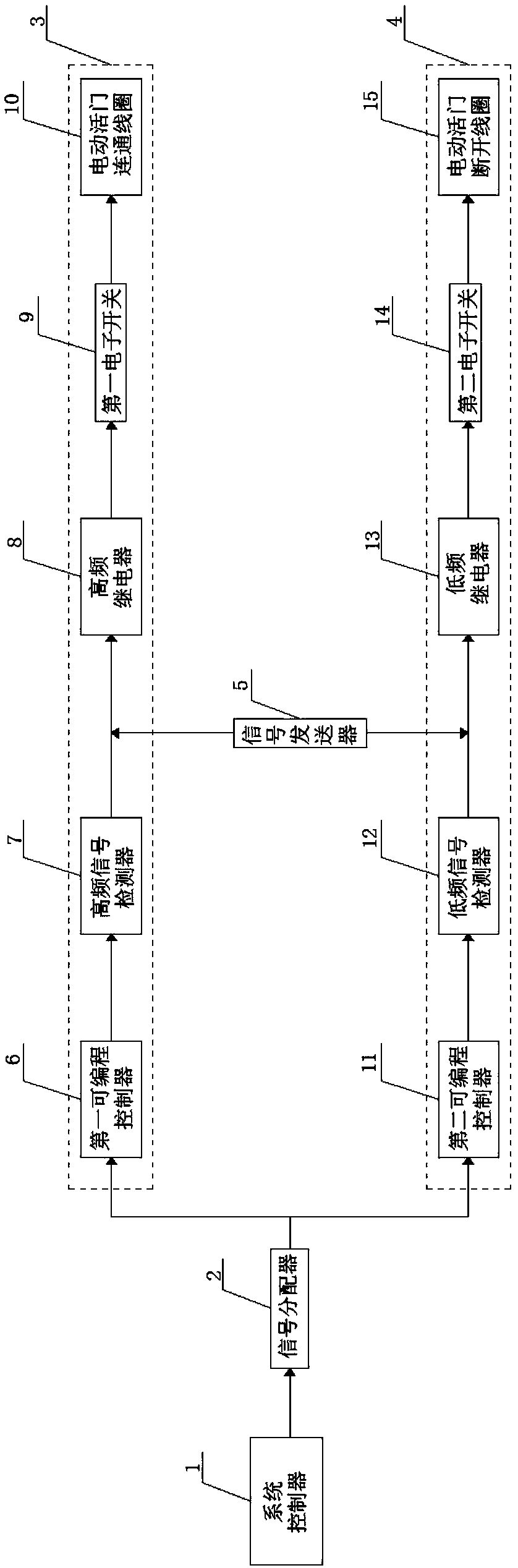
[0025] like figure 1 As shown, an electric valve interlock control system includes a system controller 1 and a signal distributor 2 connected in sequence, and the signal distributor 2 is respectively connected to a first control circuit 3 and a second control circuit 4, and the system control Device 1 is a single-chip microcomputer;

[0026] The first control circuit 3 includes a first programmable controller 6, a high-frequency signal detector 7, a high-frequency relay 8, a first electronic switch 9 and an electric valve connecting coil 10 connected in sequence, so that signals can be transmitted while After multiple inspections, the correctness of sig...


PUM


Abstract

The invention provides an electric valve interlocking control system and method. The electric valve interlocking control system comprises a system controller and a signal distributor, wherein the signal distributor is respectively connected with a first control circuit and a second control circuit; the first control circuit comprises a first programmable controller, a high-frequency signal detector, a high-frequency relay, a first electronic switch and an electric valve communicating coil which are connected in sequence; the second control circuit comprises a second programmable controller, a low-frequency signal detector, a low-frequency relay, a second electronic switch and an electric valve disconnection coil which are connected in sequence. The electric valve interlocking control system and method provided by the invention have the benefits that as the two independent control circuits are arranged, the opening and the closing of an electric valve are separately controlled; the connections of the two control circuits are respectively controlled by a high-frequency signal and a low-frequency signal, so that the possibility of error operation is reduced to a large extent; if appearing, the signal transmission error can also be detected out in time, and the signal is transmitted to another control circuit through a signal transmitter.

Description

technical field [0001] The invention belongs to the technical field of electromechanical systems, and in particular relates to an electric valve interlock control system and control method. Background technique [0002] With the continuous advancement of science and technology, electromechanical systems are widely used in production and life, and electric valves are widely used in electromechanical systems. In order to fully ensure the safety of users, the opening and closing of existing electric valves are usually operated by independent When two separate MOS tube channels are used to drive two independent coils, it should be ensured that only one of the two electromagnetic coils is powered on at the same time. If the two electromagnetic coils are powered on at the same time, it may cause damage to the electric valve. In order to prevent this from happening, software is usually used to make the output values ​​of the open electromagnetic coil and the close electromagnetic c...

Claims


Application Information

Patent Timeline
Patent Type & Authority Patents(China)
IPC IPC(8): G05B19/05
CPCG05B19/054G05B2219/1103
Inventor 魏婷
Owner 天津市美络科技发展有限公司
Features
  • R&D
  • Intellectual Property
  • Life Sciences
  • Materials
  • Tech Scout
  • Unparalleled Data Quality
  • Higher Quality Content
  • 60% Fewer Hallucinations
Learn More