Method and system for reducing the number of times of parking of motor vehicles at crossing through adoption of plane perception technology
A perception technology, a technology of parking times, applied in the traffic control system, traffic control system, instruments and other directions of road vehicles to achieve the effect of reducing the number of parking times
- Summary
- Abstract
- Description
- Claims
- Application Information
AI Technical Summary
Problems solved by technology
Method used
Image
Examples
Embodiment 1
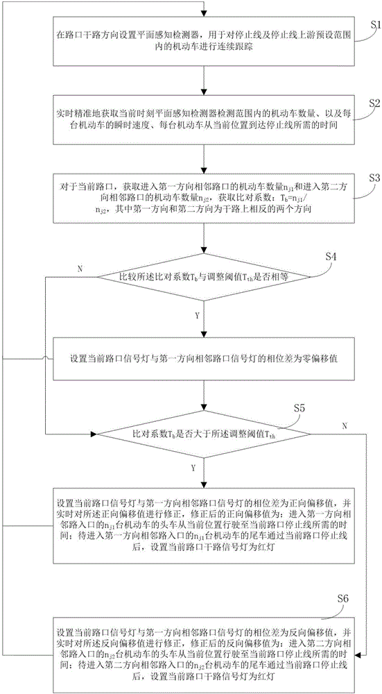
[0035] This embodiment provides a method for reducing the number of motor vehicle parking at intersections by using plane perception technology, such as figure 1 shown, including the following steps:
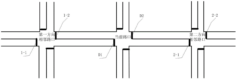
[0036] S1: Set up a plane sensing detector in the direction of the main road at the intersection, which is used to continuously track the motor vehicles within the preset range upstream of the stop line and the stop line; the preset range can cover the distance between the two stop lines at the adjacent intersection all ranges. figure 2 Give a plan view of an intersection.
[0037] S2: Accurately obtain the number of motor vehicles within the detection range of the plane perception detector at the current moment, the instantaneous speed of each motor vehicle, and the time required for each motor vehicle to reach the stop line from the current position in real time.
[0038] S3: For the current intersection, obtain the number n of motor vehicles entering the adjacent intersect...
Embodiment 2
[0045] In this embodiment, on the basis of Embodiment 1, the following improvements are made. In the step S2, the step of accurately obtaining the time required for each motor vehicle to reach the stop line from the current position in real time includes:
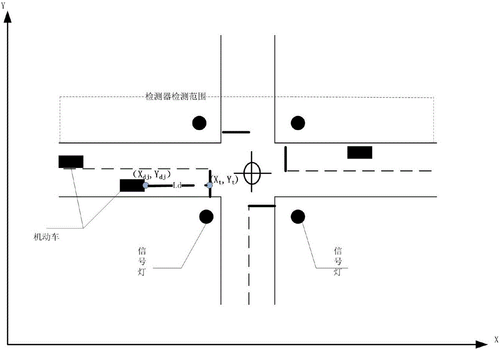
[0046] S21: the installation position coordinate data (X j ,Y j ), the coordinate data of the stop line (X t ,Y t ) marked on the electronic map; it should be noted that, for the installation location and the stop line, both occupy a certain area, so when obtaining the coordinate data, the coordinate data of the center point of the occupied area can be used as Actual coordinate data to use.
[0047] S22: Acquire the actual coordinate data (X dj ,Y dj ), and mark it on the electronic map; the motor vehicle itself has a certain area, so the coordinate data of the motor vehicle is not a point value. In practical application, you can choose the position of the center point of the front end of the motor vehicle The coordin...
Embodiment approach
[0059] As a specific implementation, the detector adopts detection radar, and also includes the following steps between step S21 and step S22:
[0060] SA1: Select the calibration flag and send the actual coordinate data of the calibration flag (X b , Y b ) marked on the electronic map, and actually measure the distance L from the radar detector to the calibration mark lb and the distance L from the correction mark to the stop line jt ; The correction sign position can be the position of the fixed markers set on the road, such as display boards, flyover bridges, utility poles, etc., and these objects will not easily shift.
[0061] SA2: Judging whether the current coordinate data (X bd , Y bd ), if it is read, the current detection error is obtained according to the current coordinate data of the correction flag and the actual coordinate data of the correction flag: (X c ,Y c )=(X bd , Y bd )-(X b , Y b ), then enter step SA3; otherwise enter step S7;
[0062] SA3: ...
PUM
 Abstract
Description
Claims
Application Information
 - R&D
- Intellectual Property
- Life Sciences
- Materials
- Tech Scout
- Unparalleled Data Quality
- Higher Quality Content
- 60% Fewer Hallucinations
Browse by: Latest US Patents, China's latest patents, Technical Efficacy Thesaurus, Application Domain, Technology Topic, Popular Technical Reports.
© 2025 PatSnap. All rights reserved.Legal|Privacy policy|Modern Slavery Act Transparency Statement|Sitemap|About US| Contact US: help@patsnap.com


