10 kilovolt protection device adapting connection end emergency adapter

A technology for protecting equipment and connecting terminals, which is applied in the direction of connection, conductive connection, clamping/spring connection, etc., and can solve the problems of economic losses of all line users, inability to maintain or replace immediately after power failure, easy contact with live phase wires, metal structures, etc.

Inactive Publication Date: 2017-01-04
耿大伟
View PDF0 Cites 0 Cited by
  • Summary
  • Abstract
  • Description
  • Claims
  • Application Information

AI Technical Summary

Problems solved by technology

[0004] In the long-term use of the drop-out fuse, the faults that often occur at the upper power supply end are: the equipment clamp is affected by the wind for a long time and the tension is too tight. In case of disconnection or disconnection (after disconnection or disconnection, it cannot be maintained or replaced immediately after power failure, and can only be stopped for a long time to be reported for approval)
What's more important is: when the T-connection wire above the equipment clamp is disconnected and swings back and forth under the wind, the end of the wire will easily touch the live phase wire and the metal frame. It is easy to cause phase-to-phase short circuit and grounding behind the wire and metal structure. When the wire end touches the live phase wire or metal structure to cause phase-to-phase short circuit and grounding, the control equipment of the main station of the power supply system will automatically trip in the shortest time. And power failure, when the power supply system main station control equipment trips immediately after power failure: because the power supply line of the power system carries many users, a sudden power failure will easily cause major economic losses to all users, especially more importantly: and Class A users connected to the same line and users involved in some special industries are more prone to greater economic losses or other unforeseen unsafe major accidents after sudden power outages

Method used


Image

  • 10 kilovolt protection device adapting connection end emergency adapter
  • 10 kilovolt protection device adapting connection end emergency adapter
  • 10 kilovolt protection device adapting connection end emergency adapter

Examples


Embodiment Construction

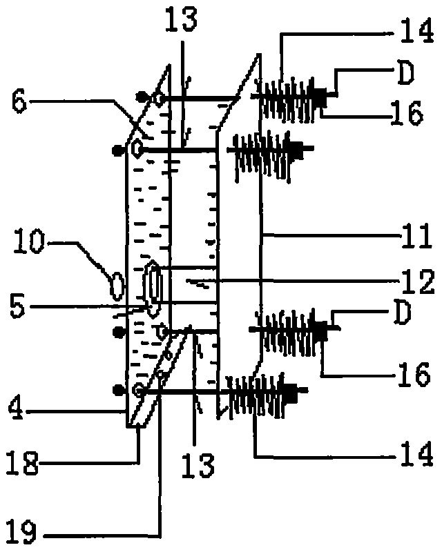
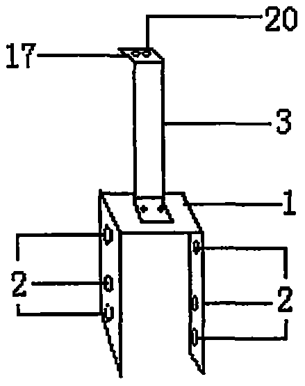
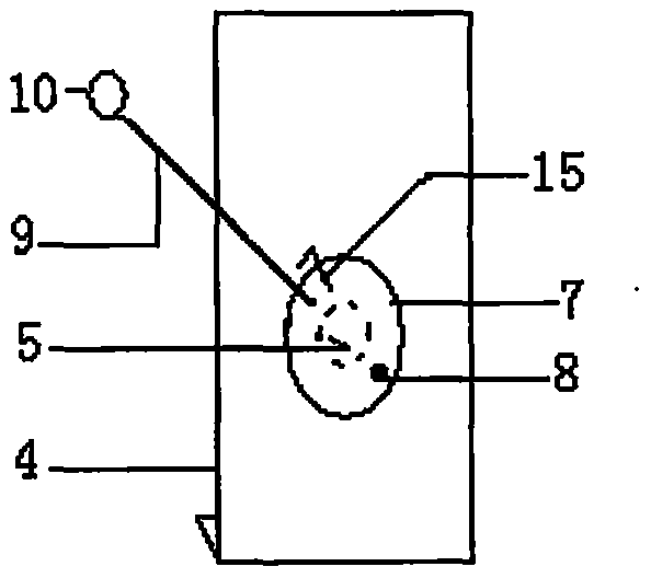
[0012] attached figure 1 , attached figure 2 shows the structure of the present invention, figure 2 Both sides of the U-shaped clamp seat 1 are provided with bolt-through holes 2, the upper end of the U-shaped clamp seat 1 is provided with a connecting plate 3, and the upper end of the connecting plate 3 is provided figure 1 The first continuous splint 4, the middle position of the lower half of the first continuous splint 4 is provided with a circular hole 5, and the first continuous splint 4 is provided with a conductive clamping thread 6, figure 1 The middle position of the outer lower half of the first connecting splint 4 is provided with a circular sealing plate 7, the lower side of the circular sealing plate 7 is provided with a riveting shaft 8, the upper side is provided with a pull rod 9, and the top of the pull rod 9 is provided with a pull ring 10. The second connecting splint 11 is arranged at the relative position of the connecting splint 4, and the circular ...


PUM


Abstract

The invention discloses a 10 kilovolt protection device adapting connection end emergency adapter. A first adapting clamp plate is provided with a circle aperture in the middle of a lower half part thereof, and the middle part of the lower half part outside the first adapting clamp plate is provided with a circle blocking plate. A second adapting clamp plate is provided with a circle penetrating pipe in the middle of a lower half part thereof. A penetrating shaft is provided with a coil spring in the outside thereof. The emergency adapter is characterized in that when the circle blocking plate in the middle of the lower half in the outside of the first adapting clamp plate blocks the circle aperture in the middle of the lower half of the first adapting clamp plate, the circle penetrating pipe in the middle of the lower half of the second adapting clamp plate does not extend outside the circle aperture in the middle of the lower half part of the first adapting clamp plate while being strutted by the adverse force of the coil spring.

Description

technical field [0001] The invention relates to a fuse protector, directly relates to an emergency connector at the connection end of a 10-kilovolt protection device, and is especially suitable for use on a high-voltage distribution line. Background technique [0002] On high-voltage transmission and distribution lines, drop-out fuses are used for overloading of distribution transformers and transmission lines, short-circuiting and opening and closing of load currents. It is a necessary high-voltage protection device for distribution transformers and transmission lines. [0003] The connection method of the drop-out fuse used for protection is as follows: the upper end of the drop-out fuse is the power supply end, the lower end is the load end, the upper end of the power supply end is connected to the T contact point of the main line by a wire clip, and the lower end is connected to the branch line or distribution transformers. [0004] In the long-term use of the drop-out ...

Claims


Application Information

Patent Timeline
IPC IPC(8): H01R4/28H01R4/48
CPCH01R4/28H01R4/4863
Inventor 耿大伟武树云陈雪峰李猛孔琳
Owner 耿大伟
Why Eureka
Try Eureka