Collection device for oil slick in sewage pond

A technology for collection devices and sewage pools, which is applied in water/sewage treatment, grease/oily substance/floating matter removal devices, water/sewage treatment equipment, etc., which can solve the problems of increased energy consumption, weak automation, and failure to achieve oily water Separation and other issues to achieve the effect of reducing processing difficulty, automation and flexibility

Pending Publication Date: 2020-02-04
ANHUI CHUJIANG TECHCAL NEW MATERIAL CO LTD
View PDF0 Cites 0 Cited by
  • Summary
  • Abstract
  • Description
  • Claims
  • Application Information

AI Technical Summary

Problems solved by technology

[0006] The purpose of the present invention is to overcome the need for manual adjustment during the oil slick collection process in the sewage tank in the prior art, the automation is not strong, and the oil-water separation has not been achieved, the oil-water mixing in the slick oil collection process, the oil removal effect is not good, and the increase In order to meet the shortage of energy consumption and other issues, a kind of oil slick collection device for sewage pool is provided. By adopting the technical scheme of the present invention, the oil and water can be completely separated, so that the slop oil can be collected and treated separately, reducing the difficulty of sewage treatment and conforming to the concept of environmental protection. At the same time, the slick Automated and flexible oil collection unit

Method used


Image

  • Collection device for oil slick in sewage pond
  • Collection device for oil slick in sewage pond
  • Collection device for oil slick in sewage pond

Examples


Embodiment 1

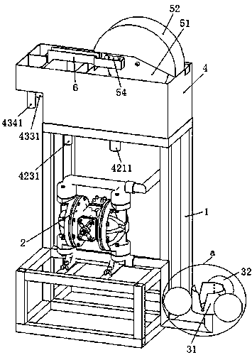
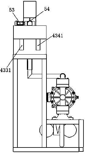
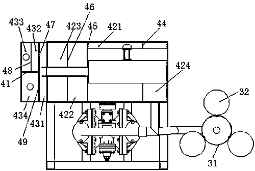
[0036] combine figure 1 , figure 2 , image 3 , Figure 4 and Figure 5 , a floating oil collection device for a sewage tank in this embodiment, comprising a bracket 1 and an oil-water separation box 4 arranged on the bracket 1, the top of the oil-water separation box 4 is provided with an oil flow tank 6, and the inside of the oil-water separation box 4 is arranged along the left and right direction. A secondary oil-water separation area and a primary oil-water separation area are provided in sequence, wherein an oil scraping rotating mechanism is arranged on the upper part inside the primary oil-water separating area, and the oil scraping rotating mechanism includes a turntable 51, a turntable cover 52 arranged on the top of the turntable 51 and a drive turntable 51 rotates the servo motor 53, one end of the above-mentioned oil flow groove 6 extends to the left to form an oil outlet connected to the above-mentioned secondary oil-water separation area, and the other end o...


PUM


Abstract

The invention discloses a collection device for oil slick in a sewage pond, and belongs to the field of sewage treatment. The device includes an oil-water separation tank, the top of the oil-water separation tank is provided with an oil flow groove, the interior of the oil-water separation tank is provided with a secondary oil-water separation zone and a primary oil-water separation zone in the left-right direction, the upper part of the interior of the primary oil-water separation zone is provided with a rotating disc, the oil outlet end of the oil flow groove is connected to the secondary oil-water separation zone, and the other end of the oil flow groove is provided with a rectangular groove for placing two sides of the rotating disc; two oil scraping sheets are obliquely symmetricallyarranged on two sides of the rotating disc, one end of each oil scraping sheet abuts against the end surface of one side of the rotating disc, and the other end of each oil scraping sheet faces downwards to the bottom of the oil flow groove; and the bottom of the secondary oil-water separation zone is provided with a secondary water discharge opening and an oil discharge opening, the bottom of theprimary oil-water separation zone is provided with a primary water discharge opening, and the primary oil-water separation zone is connected to an oil suction floating mechanism through a pipeline. By adopting the technical solution of the invention, oil-water complete separation can be achieved, dirty oil can be collected and treated separately, and the difficulty of sewage treatment can be reduced.

Description

technical field [0001] The invention relates to the technical field of sewage treatment, and more specifically relates to a sewage pool floating oil collection device. Background technique [0002] In the process of copper strip processing, there will always be processes such as smelting ingots, milling, hot rolling, rough rolling, annealing, primary cleaning, finished product rolling, and secondary cleaning, and emulsion lubrication is required for the rolls during the rolling process , but in this production process, there will always be oil leaked from the equipment and the mineral oil in the emulsion itself will be demulsified to form dirty oil. When the wastewater from the rolling process is discharged into the sewage pool, there will always be a lot of oil. If things go on like this The oil pollution in the sewage pool is more and more serious. The main pollutant in the sewage is grease, which has a high content in the sewage, which brings a high load to the sewage tre...

Claims


Application Information

Patent Timeline
Patent Type & Authority Applications(China)
IPC IPC(8): C02F1/40
CPCC02F1/40C02F2201/007
Inventor 陈剑刘建新孙来保周明田威马子超
Owner ANHUI CHUJIANG TECHCAL NEW MATERIAL CO LTD
Why Eureka
Try Eureka