Check patentability & draft patents in minutes with Patsnap Eureka AI!

Interface protection device and protection method

An interface protection, in-device technology, applied in the interface field, can solve problems such as increasing production cost and workload, short circuit of power supply on wearable devices, cumbersome plugging and unplugging of rubber plugs, etc.

Active Publication Date: 2017-01-04
WATCHDATA SYST
View PDF5 Cites 5 Cited by
  • Summary
  • Abstract
  • Description
  • Claims
  • Application Information

AI Technical Summary

Problems solved by technology

[0004] see figure 1 One of the schematic diagrams of the contact-type wearable device is shown. Since the contacts of the wearable device are directly exposed on the surface of the device, the contacts are splashed with water, wet, etc., which will cause a short circuit of the power supply on the wearable device, thereby causing Damage to wearables
In this regard, the commonly used protection or waterproof design is usually to add a rubber plug (see figure 2 The schematic diagram of the contact wearable device shown in the second), when charging the wearable device or exchanging data with the wearable device through the device contact, the rubber plug does not block the device contact, in other cases, the rubber plug is used to block live device contacts, however, figure 2 The design shown will not only increase the production cost and workload, but the cumbersome operation of inserting and pulling out the rubber plug and using the rubber plug to block the contacts for a long time will also make the rubber plug easy to fall off

Method used


Image

  • Interface protection device and protection method
  • Interface protection device and protection method
  • Interface protection device and protection method

Examples


Embodiment 1

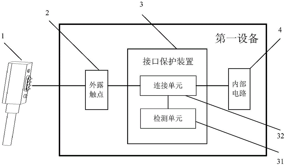
[0064] see image 3 , is one of the schematic diagrams of the interface protection device provided by the embodiment of the present invention, the interface protection device 3 is built in the first device, the interface protection device 3 includes a detection unit 31 and a connection unit 32, and the connection unit 32 is respectively It is connected with the exposed contact 2 of the first device, the internal circuit 4 of the first device and the detection unit 31 .

[0065] The detection unit 31 is configured to send a connection signal to the connecting unit 32 when the external wire 1 is close to or connected to the exposed contact 2; when the external wire 1 is away from or disconnected from the exposed contact 2, A connection signal is not sent to the connection unit 32; the external line 1 is a data line or a charging line of the first device.

[0066] The connection unit 32 is configured to connect the exposed contact 2 with the internal circuit 4 when receiving the...

Embodiment 2

[0069] see Figure 4 In the second schematic diagram of the interface protection device shown, on the basis of the first embodiment above, the detection unit 31 may specifically be a magnetic switch 311, and the external wire 1 is a magnetic contact type external wire.

[0070] The magnetic switch 311 is used to close when the external wire 1 is close to or connected to the exposed contact 2, and output an electrical signal to the connection unit 32; when the external wire 1 is away from or disconnected from the exposed When the contact 2 is disconnected, no electrical signal is output to the connection unit 32; the electrical signal is the connection signal.

[0071] The connection unit 32 is configured to connect the exposed contact 2 with the internal circuit 4 when receiving the on signal sent by the magnetic switch 311; When the signal is turned on, the exposed contact 2 is disconnected from the internal circuit 4 .

[0072] In Embodiment 2 of the present invention, it ...

Embodiment 3

[0076] see Figure 5 The third schematic diagram of the interface protection device shown, on the basis of the first embodiment above, the detection unit 31 includes a magnetic switch 312 and a detection module 313, and the detection module 313 is respectively connected to the exposed contact 2, the The magnetic switch 312 is connected to the connection unit 32, the external wire 1 is a magnetic contact type external wire, the external wire 1 includes a first contact connected to the ground wire, and the exposed contact 2 passes through a series resistance Connect with the power cord of the first device.

[0077] The magnetic switch 312 is used to close when the external wire 1 is close to or connected to the exposed contact 2, and output an electrical signal to the detection module 313; when the external wire 1 is away from or disconnected from the exposed When the contact 2 is disconnected, no electrical signal is output to the detection module 313;

[0078] The detection ...


PUM


Abstract

The invention discloses an interface protection device. The interface protection device is arranged in a first device and comprises a detection unit and a connection unit, wherein the connection unit is connected with an exposed contact of the first device, an internal circuit of the first device and the detection unit, the detection unit is used for sending a connection signal to the connection unit when an external wire gets close to or is connected with the exposed contact and is not used for sending the connection signal to the connection unit when the external wire deviates from or is disconnected with the exposed contact, the external wire is a data line or a charging line of the first device, and the connection unit is used for making the exposed contact and the internal circuit connected when the connection signal sent by the detection unit is received and making the exposed contact and the internal circuit disconnected when the connection signal sent by the detection unit is not received. The invention also discloses an interface protection method.

Description

technical field [0001] The invention relates to the field of interface technology, in particular to an interface protection device and a protection method. Background technique [0002] A wearable device refers to a portable device that can be directly worn on the body or integrated into the user's clothes or accessories, such as a wrist-supported watch device (including products such as watches and wristbands). [0003] Current wearable devices, due to limited size, mostly use contact interface design. Such interfaces are mostly used to charge wearable devices, communicate with computers to exchange data, or update firmware and download programs when the device leaves the factory. Wait. [0004] see figure 1 One of the schematic diagrams of the contact-type wearable device is shown. Since the contacts of the wearable device are directly exposed on the surface of the device, the contacts are splashed with water, wet, etc., which will cause a short circuit of the power supp...

Claims


Application Information

Patent Timeline
Patent Type & Authority Applications(China)
IPC IPC(8): H01R13/66H01R13/70H01R13/713H01R43/00H01R43/26
Inventor 周卫国吕争荣
Owner WATCHDATA SYST
Features
  • R&D
  • Intellectual Property
  • Life Sciences
  • Materials
  • Tech Scout
  • Unparalleled Data Quality
  • Higher Quality Content
  • 60% Fewer Hallucinations
Learn More