Automatic heat shrink tubing sleeving device

A technology for covering heat-shrinkable tube and sleeve device, which is applied in the field of automatic heat-shrinkable tube device

Active Publication Date: 2017-01-04
GUANGDONG XG INTELLIGENT SYST CO LTD
View PDF9 Cites 2 Cited by
  • Summary
  • Abstract
  • Description
  • Claims
  • Application Information

AI Technical Summary

Problems solved by technology

At present, when the heat shrinkable tube is put on the wire joint of the wire reel, it can only be operated manually

Method used


Image

  • Automatic heat shrink tubing sleeving device
  • Automatic heat shrink tubing sleeving device

Examples


Embodiment Construction

[0019] Below in conjunction with accompanying drawing and embodiment the present invention is described in detail:

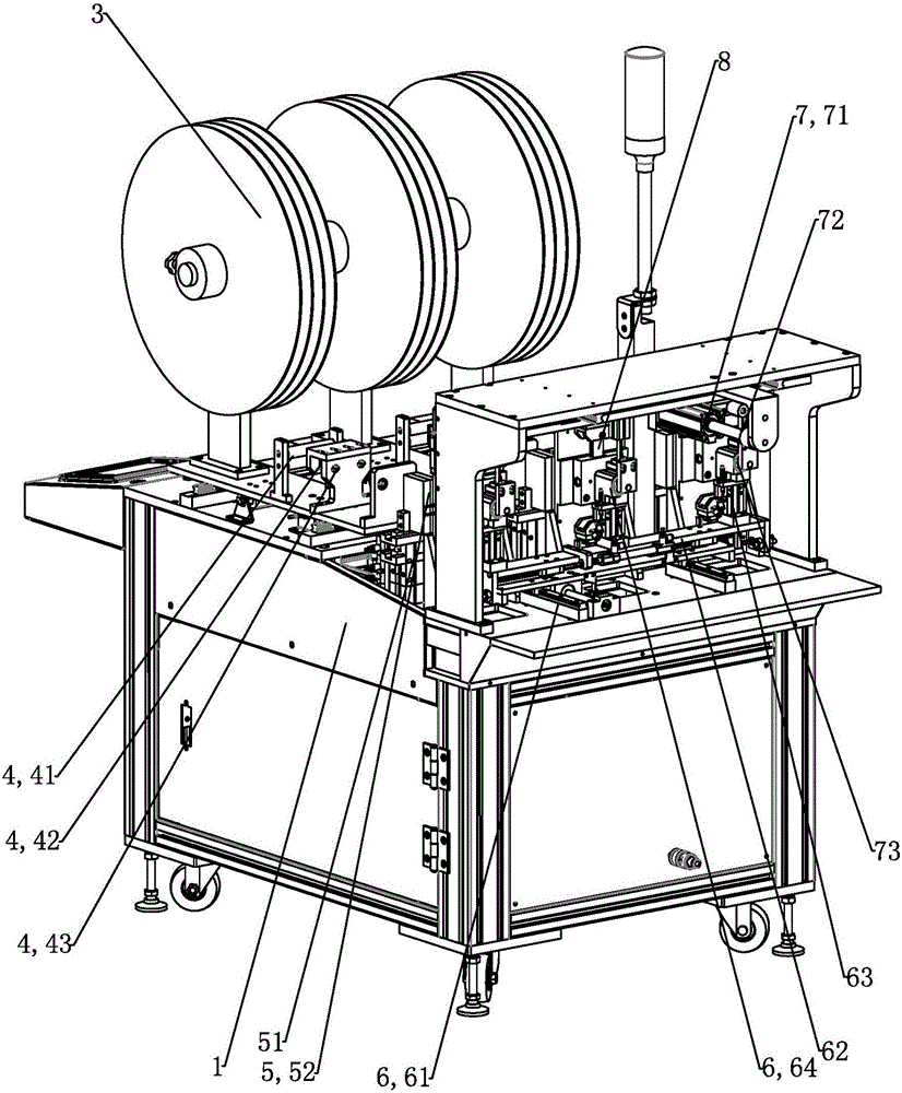
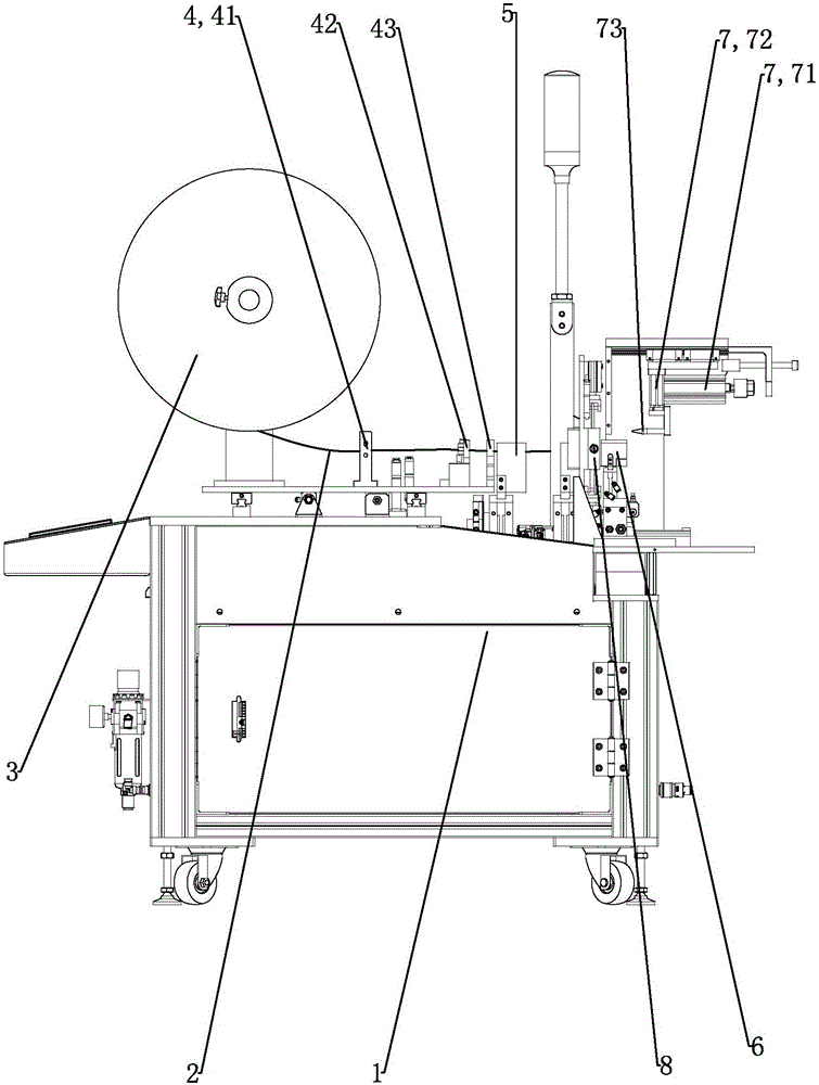
[0020] As shown in the figure, the automatic heat-shrinkable tubing device includes a frame platform 1 on which a tube coil 3 coiled with a heat-shrinkable tube 2 is arranged. A shaping device 4 for shaping the heat-shrinkable tube 2 pulled out from the tube tray 3 is provided on the frame platform 1 . A feeding mechanism 5 for feeding the heat-shrinkable tube 2 forward is provided in front of the shaping device 4 . In front of the feeding mechanism 5, there is a casing device 6 that can clamp the heat-shrinkable tube 2 and a cutter mechanism 8 that cuts the heat-shrinkable tube 2 sent to the casing device 6. On the frame platform 1 A rounding mechanism 7 that can round the heat-shrinkable tube 2 in the casing device 6 is provided on the top. In this embodiment, there are three sets of tube disk 3, shaping device 4, feeding mechanism 5, casing device 6, cutter...


PUM


Abstract

The invention discloses an automatic heat shrink tubing sleeving device. The device comprises rack platform, on which there is a tube plate coiled with heat shrink tubing, and a reshaping device for reshaping the heat shrink tubing drawn from the tube plate; in front of the reshaping device there is a feeding mechanism conveying forward the heat shrink tubing for material feeding; in front of the feeding mechanism there is a tube sleeving device which can clamp and sleeve the heat shrink tubing and a cutting mechanism which can cut the heat shrink tubing sent into the tube sleevingd device; on the rack platform there is a rounding mechanism which can round the heat shrink tubing in the tube sleeving device. The invention has the advantage of labor cost saving, high efficiency and etc.

Description

[0001] 【Technical field】 [0002] The invention relates to an automatic sleeve heat-shrinkable tube device. [0003] 【Background technique】 [0004] At present, when producing the wire reel of the induction cooker, it is necessary to cover the output end of the wire reel with a high-temperature heat-shrinkable tube to prevent high-temperature leakage. At present, when the heat-shrinkable tube is sleeved on the wire joint of the wire reel, it can only be operated manually. [0005] 【Content of invention】 [0006] The purpose of the present invention is to overcome the deficiencies of the prior art and provide a labor-saving, high-efficiency automatic sleeve heat-shrinkable tube device. [0007] For above-mentioned purpose, the present invention adopts following technical scheme: [0008] The automatic sleeve heat-shrinkable tube device is characterized in that it includes a frame platform 1, a tube coil 3 coiled with a heat-shrinkable tube 2 is provided on the frame platform ...

Claims


Application Information

Patent Timeline
Patent Type & Authority Applications(China)
IPC IPC(8): H01R43/20
Inventor 邓朋飞
Owner GUANGDONG XG INTELLIGENT SYST CO LTD
Why Eureka
Try Eureka