Metal sheathed heater using splice connection assembly with heat shrinkable tubing, and method of use

a technology of splice connector and heater, which is applied in the direction of insulated conductors, cable terminations, cables, etc., can solve the problems of time-consuming and costly procedure, the end of resistance wires and/or the end of stranded lead wires may not be properly captured by the splice connector, and the use of silicone wiring for the heater cable and lead wires. , to achieve the effect of less cost, less diameter and more durabl

Inactive Publication Date: 2007-06-12
TUTCO
View PDF8 Cites 26 Cited by
  • Summary
  • Abstract
  • Description
  • Claims
  • Application Information

AI Technical Summary

Benefits of technology

[0023]Yet another object of the invention is a metal sheathed heater that employs at least lead wires that do not use silicone as insulating material, thus allowing the lead wires to be made with tougher resistance to cutting and, if desired, smaller diameter. Cost savings are also realized by the elimination of costly silicone.
[0027]While the heater cable and lead wire can have the same insulation, the lead wire can have a different insulation such as a non-silicone type, thereby allowing more durable, smaller diameter, and / or less expensive lead wires to be employed as part of the metal sheathed heater.
[0028]In another aspect of the invention, a section of the metal sheath surrounding the heat shrinkable tubing can have an enlarged diameter as compared to remaining sections surrounding the heater cable, thus accommodating the increased diameter section of the splice connection.
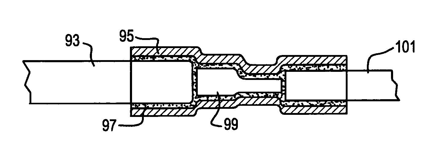
[0030]The invention also includes the splice connection for each end of an insulated heater cable and an end of an insulated lead wire wherein a connector links one end of the heater cable with one end of the lead wire. The splice connection comprises an adhesive covering the connector, the end of the lead wire, and the end of the heater cable. The heat shrinkable tubing covers the connector and ends of the heater cable and lead wire, the tubing being bonded to the adhesive. The insulation of the lead wire and insulation of the heater cable can be one of the same material with the material being silicone; different materials with the heater cable insulation being silicone; and the same material with each not being silicone. Preferably, the insulation of the heater cable is silicone, and the insulation of the lead wire is a material different from silicone. Another preference is to employ lead wires that have more durable properties than lead wires having silicone insulation, and as such, smaller diameter lead wire can be utilized for additional cost savings.

Problems solved by technology

This procedure is both time-consuming and costly.
One of the problems with prior art heaters is the use of silicone wiring for the heater cable and lead wires.
Also, the ends of the resistance wire and / or the ends of the stranded lead wires may not be properly captured by the splice connector.
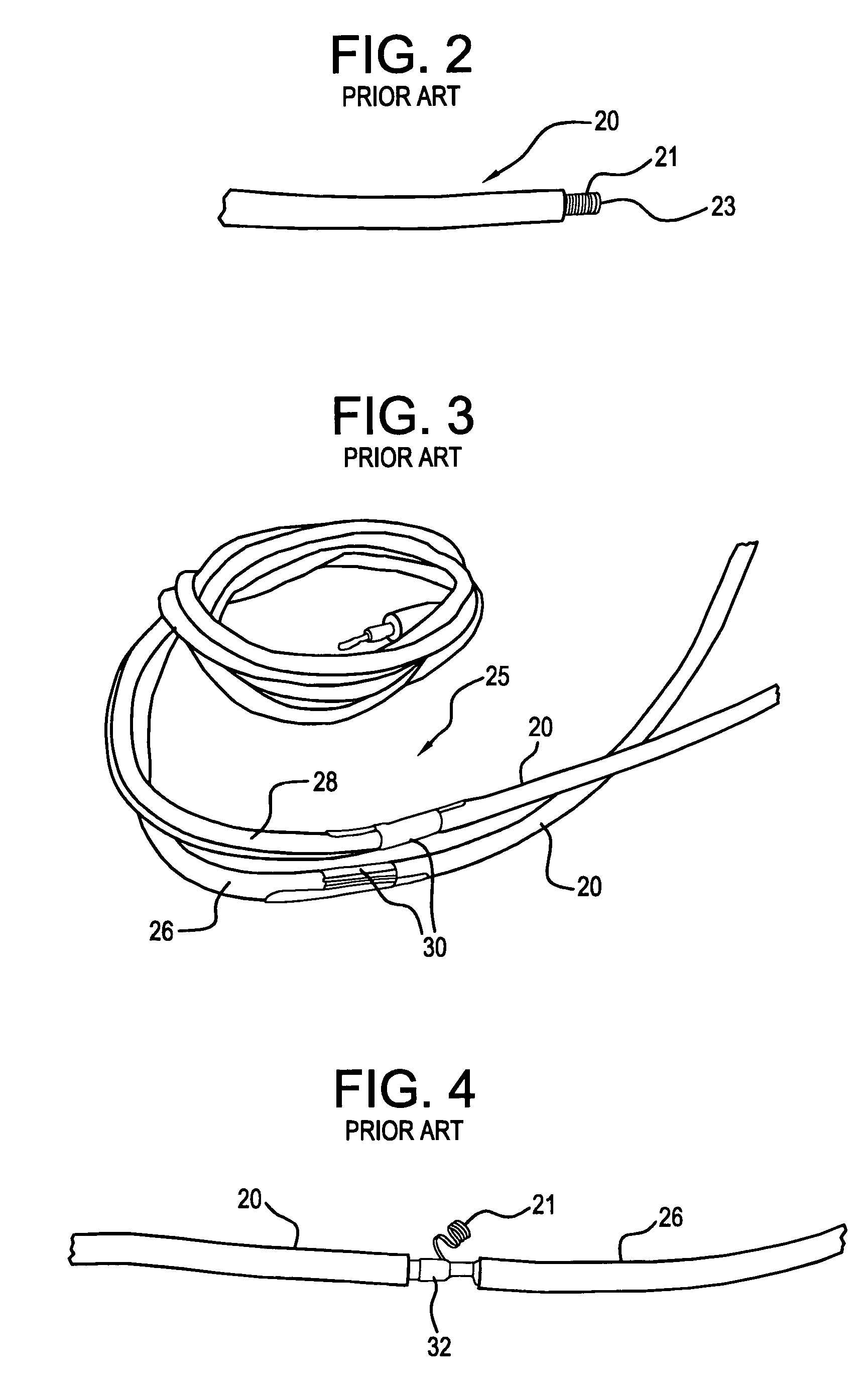
Also, if the mold section is at a diameter larger than that of the wires, the mold section 30 can or will be cut when the metal sheath is formed around the assembly resulting in either improper heater operation or failure.
Such a flaw can result in either improper operation or failure of the heater.
However and during the manufacture of these CH model heaters, a number of hard to identify conditions can occur that, if are not detected prior to using, the heater can fail.
These conditions could be breaks, cracks or incomplete bonding between the wire insulation and the mold material resulting in heater failure.
Also, should either the end of a heater core wire or the end of a lead wire strand protrude outside the splice connector and extend a distance equal to or greater than the distance to the outer surface of the molded section, a direct electrical path to the metal heater sheath is created resulting in heater failure, (See FIG. 4).
Further, if either a piece of fiberglass from the core wire or some of the powdered talc used to coat the silicone insulation becomes imbedded in the mold area, a defect can occur resulting in heater failure.
Another hard to identify defect is either very tiny holes or cuts in the heater cable adjacent to the mold sections that are not sealed by the molding silicone.
These holes and cuts result when the tools used in performing these operations becomes worn or out of adjustment and impinge on the insulation covering the wires with sufficient force to cut through to the metal underneath.
It does not work to cover all the defect types mentioned above by making the mold section to a diameter larger than the wire diameter and extend it to cover any possible holes or cuts in the insulation as mentioned above.
This is because molded sections, larger in diameter than the wires, will be cut and rendered defective when the metal sheath is applied as described above.
Another problem with the prior art is that it is not possible to use lead wires with insulation other than silicone because only silicone will bond to silicone.
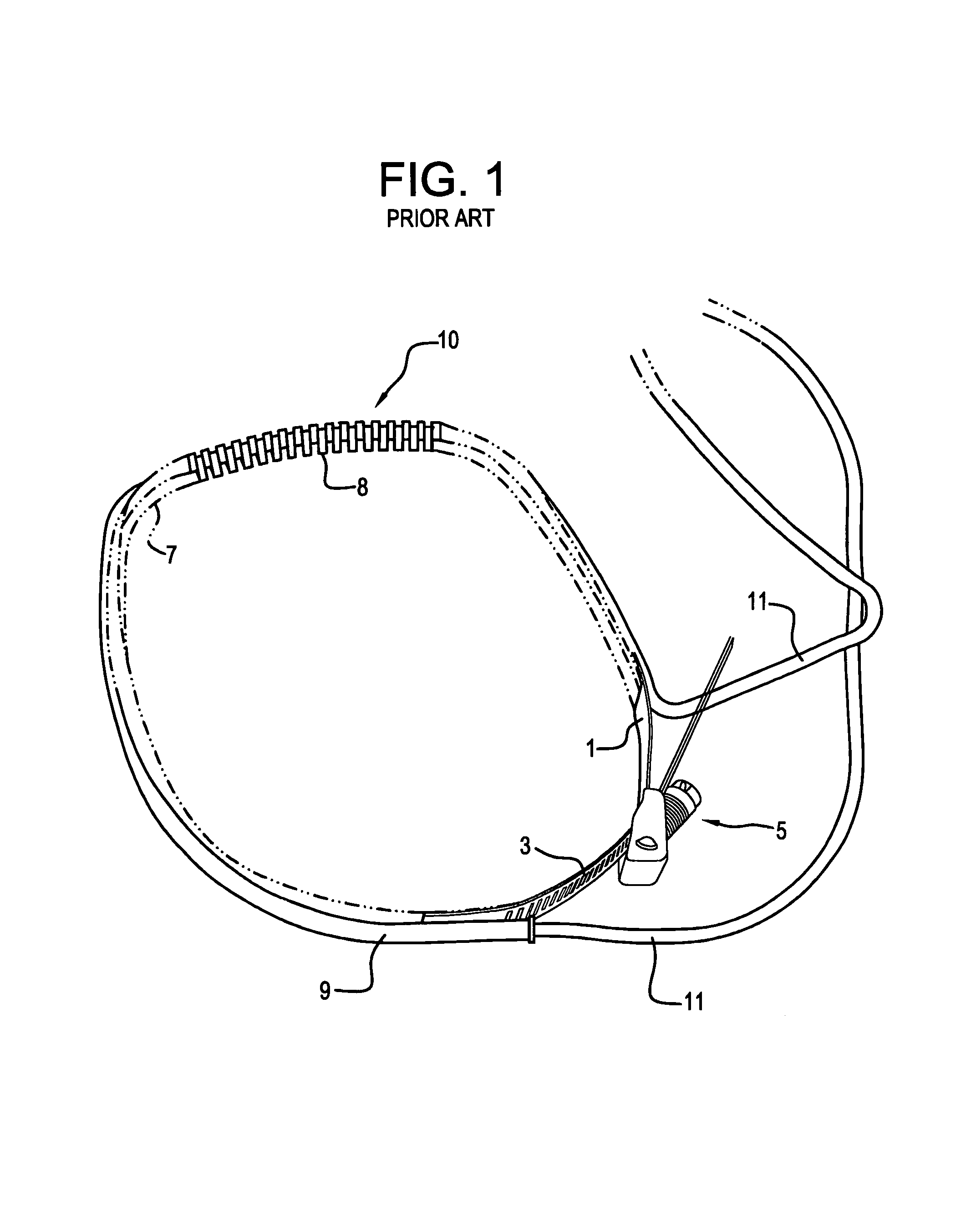
Often times, the ends of the formed sheath have sharp edges and when the heater is installed in its intended location it is possible for the soft silicone lead wire insulation to accidentally be forced against a sharp edge cutting deep enough to create a defect.

Method used


Image

  • Metal sheathed heater using splice connection assembly with heat shrinkable tubing, and method of use
  • Metal sheathed heater using splice connection assembly with heat shrinkable tubing, and method of use
  • Metal sheathed heater using splice connection assembly with heat shrinkable tubing, and method of use

Examples


Embodiment Construction

[0041]The present invention offers significant improvements in the field of metal sheathed heaters, including the heaters themselves, and their methods of making and using. By eliminating the molding operation using a silicone compound to insulate the splice connection surrounded by the metal sheath, tougher lead wires can be used, improved pulling resistance can be obtained, improved sealing and protection of the splice area are realized, and costs are reduced by eliminating silicone lead wires.

[0042]FIG. 6 shows one aspect of the improved metal sheathed heater, wherein a section 50 near the end of a metal sheath 51 has a diameter slightly larger than the remainder of the sheath. This drawing also shows the clamp end 53 welded to an end of the sheath. It should be noted that the welding operation wherein the clamp end and teeth are welded together causes the teeth to become part of the clamp end. This same enlarged diameter section 50 is found on the opposite end of the metal sheat...


PUM

PropertyMeasurementUnit
diameteraaaaaaaaaa
flexibleaaaaaaaaaa
mechanicalaaaaaaaaaa

Abstract

A metal sheathed heater utilizes splice connections that connects ends of a heater cable with ends of a lead wire. Each splice connection has a connector that connects core wires of the lead wires and heater cable together. Heat shrinkable tubing surrounds the connector and ends of the heater cable and lead wires. An adhesive is interposed between the heat shrinkable tubing and heater cable and lead wire ends to bond with the heat shrinkable tubing and complete the splice connection. The metal sheath of the heater can be formed with an enlarged diameter portion to account for the heat shrinkable tubing surrounding the lead wire and heater cable ends.

Description

[0001]This application claims priority under 35 USC 119(e) based on provisional patent application No. 60 / 549,145 filed on Mar. 3, 2004.FIELD OF THE INVENTION[0002]The present invention is directed to a metal sheathed heater and a splice connection assembly therefore, and in particular, to the use of a heat shrinkable tube and adhesive combination for sealing the splice connection assembly.BACKGROUND ART[0003]The use of electric belly-band heaters is well known in the prior art. Typically, these heaters use resistance heating wherein a resistance heating wire or heater cable is encased in a metal sheath. The metal sheath is in contact with the item or material to be heated. One type of belly-band heater (commonly referred to as a “crankcase heater”, “compressor heater” or “sump heater”) is used to heat refrigeration compressors or air-conditioning compressors. The heater can employ a standard hose clamp or other type of clamping arrangement for attachment to the compressor. The stan...

Claims


Application Information

Patent Timeline
Patent Type & Authority Patents(United States)
IPC IPC(8): H05B3/08H01R4/00H01R43/00H01R4/72H05B3/06H05B3/56H05B3/58
CPCH01R4/72H05B3/06H05B3/56Y10T29/49195Y10T29/49172Y10T29/49101H01B7/20
Inventor KIRBY, ROBERT
Owner TUTCO
Why Eureka
Try Eureka