
Dual voltage circuit tester

a circuit tester and dual-voltage technology, applied in the field of voltage testers, can solve the problems of increasing the risk of manufacturer losing customers, increasing the cost of power supplies, and increasing the cost of testing, so as to achieve the effect of quick determination

Inactive Publication Date: 2005-03-17
SNAP ON INC
View PDF4 Cites 27 Cited by
  • Summary
  • Abstract
  • Description
  • Claims
  • Application Information

AI Technical Summary

Benefits of technology

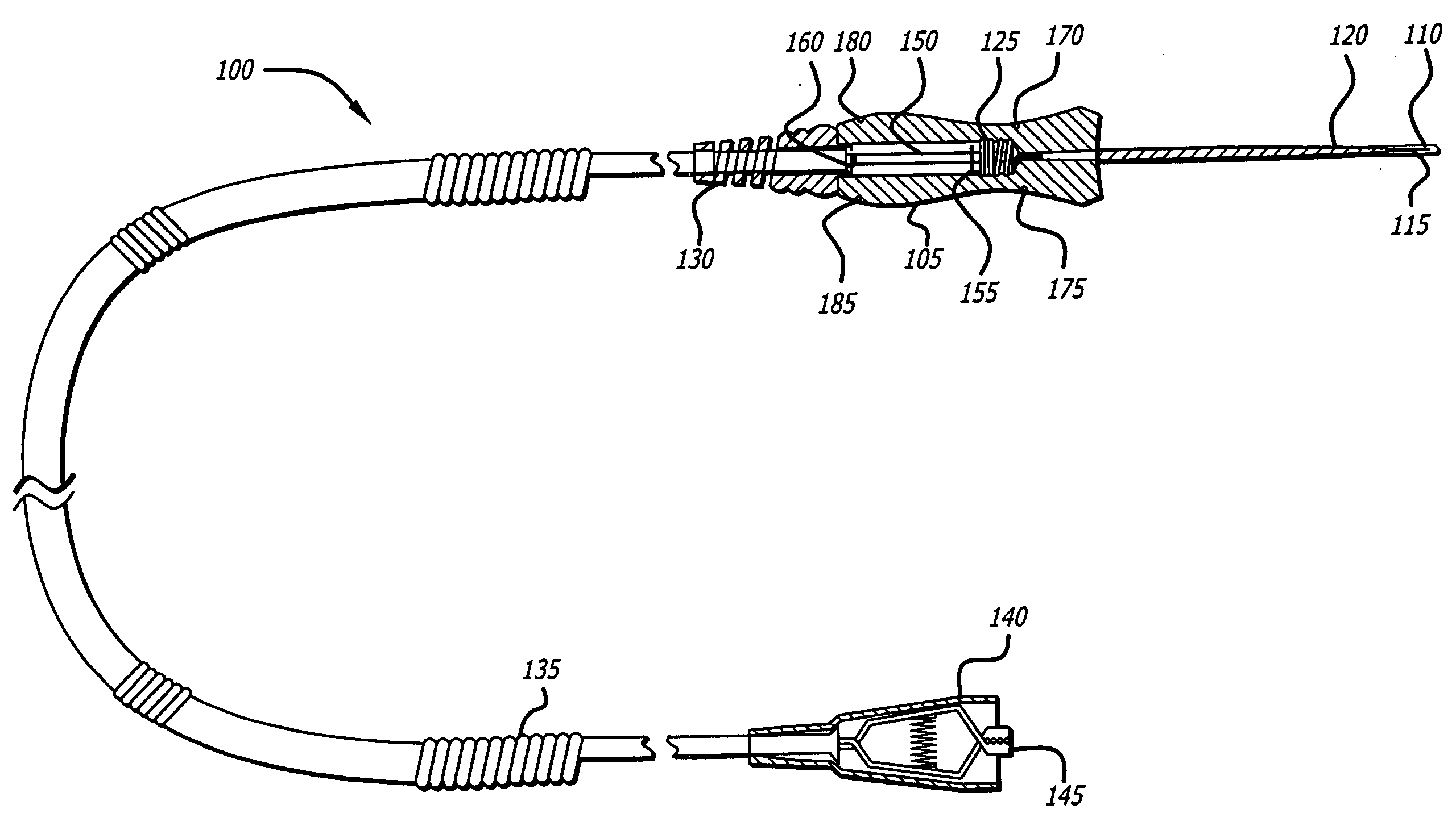
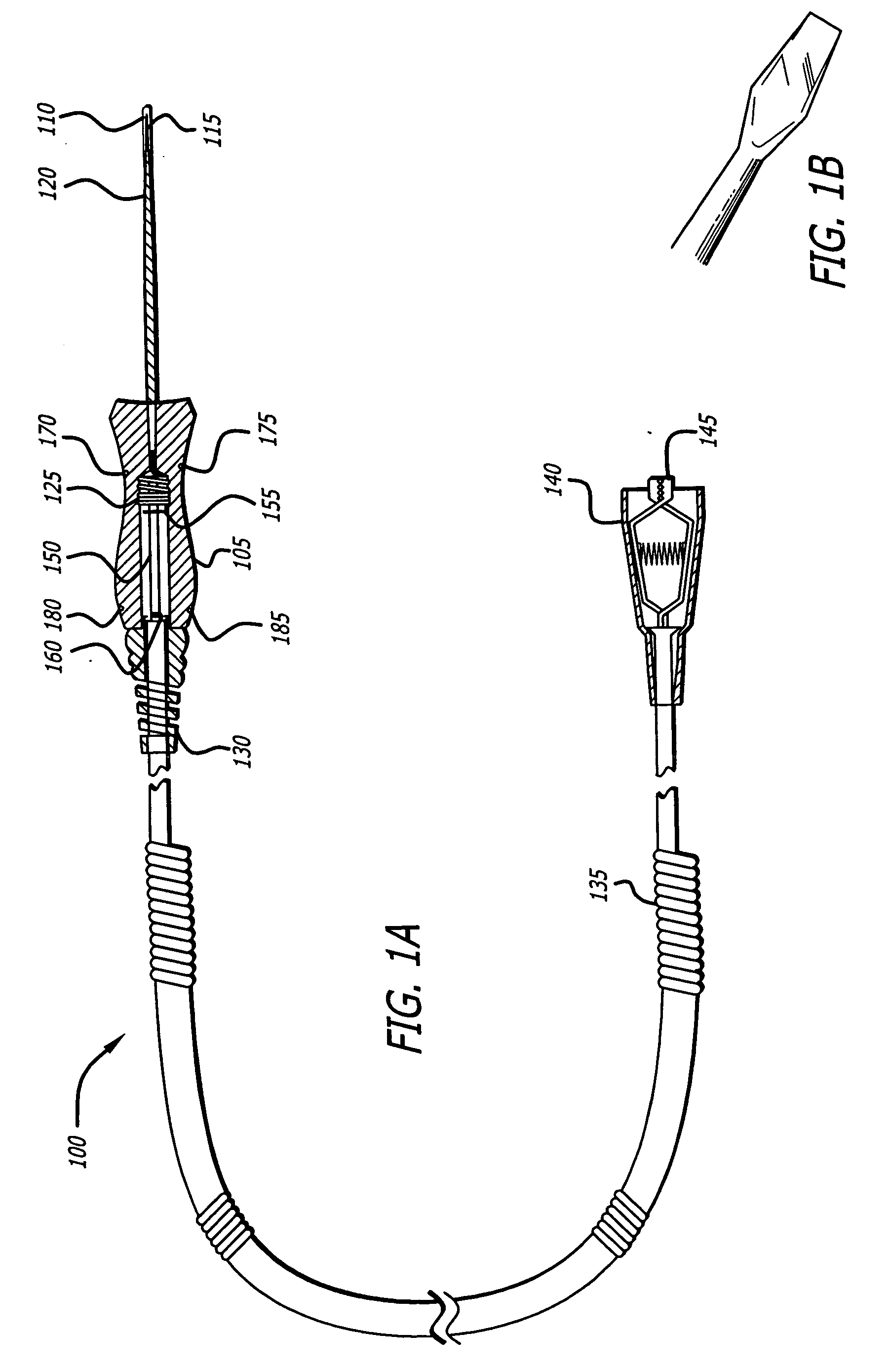
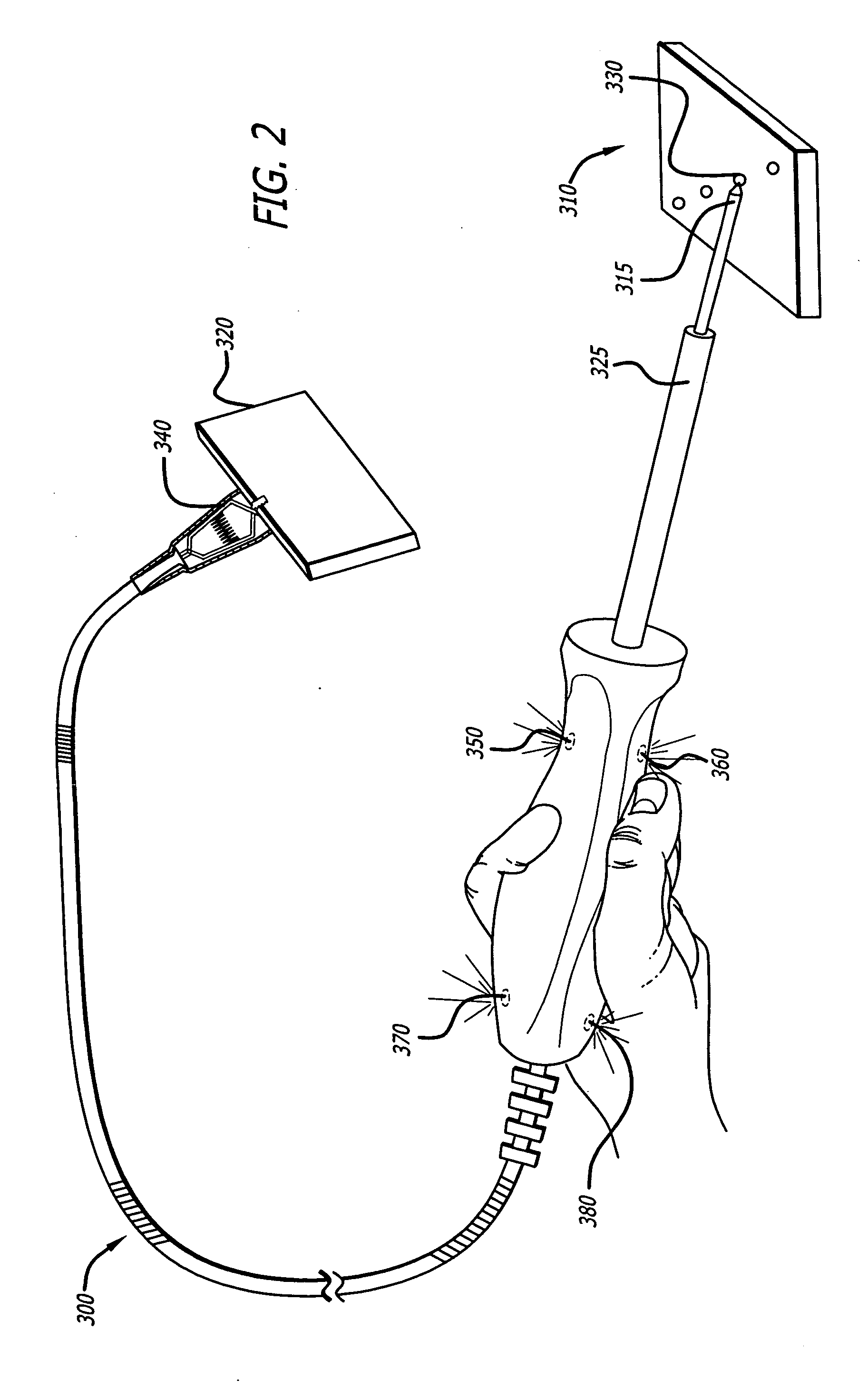
The present patent provides an efficient way to determine the voltage at which an automotive electrical system operates. It includes a circuit tester with a curved handle, screwdriver-type probe tip, and ground clip that can be easily gripped by a technician. The tester also includes electrical circuitry that senses low and high automotive system voltages and emits light of different colors to inform the technician of the voltage level. The tester is designed to be safe and includes heat shrink tubing, strain relief, insulator boots, and a retractable coil cord for easy stowing and a cap to protect the probe tip. The method involves connecting the probe tip to the positive side of an automotive circuit, connecting the ground clip to the negative side of an automotive circuit, and determining the voltage level based on the indicators on the visible display. The electrical circuit is relatively inexpensive and includes a first and second voltage sensing device that senses low and high automotive system voltages, respectively. The circuit also includes a number of resistors to protect against overdriving the diodes and burning them out. The present patent provides an easy-to-use, handheld circuit tester and method that assists a technician in quickly determining the voltage level at which an automotive electrical system operates.

Problems solved by technology

These higher voltage systems can be expensive and relatively complex when compared to the traditional 12-14 volt systems.
Greater power supplies were generally more expensive, and the manufacturer would be required to pass this cost on to the consumer.
By substantially increasing the prices of its vehicles, a manufacturer risked losing customers.
Moreover, the complexity of such systems required a re-design of automotive electrical systems so that they could support these higher voltages.
The manufacturer risked losing customers because the customer demanded such features.

Method used


Image

  • Dual voltage circuit tester
  • Dual voltage circuit tester
  • Dual voltage circuit tester

Examples


Embodiment Construction

[0023] The present disclosure relates to a tester, circuit and method for testing the voltage level of an automotive electrical circuit. The substantially screwdriver-shaped tester allows a technician to promptly determine whether the technician is testing a 12-14 volt circuit or a 36-42 volt circuit. This voltage level determination is made based on the color of light emitting diodes on the tester's visual display. A blue light emitting diode indicates a voltage of 12-14 volts is being sensed, while both red and blue light emitting diodes indicate a voltage level of 36-42 volts is being sensed. At times, the voltage drop of about 12-14 volts is hereinafter referred to as a low automotive system voltage, while the voltage drop of about 36-42 volts is hereinafter at times referred to as a high automotive system voltage. These voltage drops are measured with reference from the positive side of an automotive electrical circuit to the negative side of the same electrical circuit.

[0024]...


PUM


Abstract

A handheld dual voltage circuit tester, method and electronic circuit that quickly allows a technician to determine whether an automotive electrical system runs on a 12-14 volt circuit or 36-42 volt circuit. The tester may be used for automobiles having a single voltage electrical system, or automobiles with distinct electrical systems operating on one of a 12-14 volts circuit or a 36-42 volt circuit. The tester includes a screwdriver-type elongated handle and probe tip. The tester also includes electronic circuitry disposed within its handle, heat shrink tubing, a conductive spring assembly, a strain relief, a retractable coil cord, a ground clip and insulation that encloses the ground clip. The tester also includes electronic circuitry that emits light of a first color when a 12-14 volt circuit is sensed, and light of a second color when a 36-42 volt circuit is sensed.

Description

FIELD OF THE DISCLOSURE [0001] The present disclosure relates to voltage testers, and more particularly to efficiently determining whether an automotive electrical system operates at 12-14 volts or 36-42 volts. BACKGROUND OF THE DISCLOSURE [0002] Electrical circuit testers are well known in the art, and are commonly used by electricians as well as laypersons. Such testers are also used by automotive technicians to determine the voltage at which an automotive electrical system operates. Until recent years, automotive electrical systems typically incorporated a power supply of 6-12 volts, generally through a battery. Accordingly, a 6-12 volt circuit tester was used to determine the voltage level of power supplied to these systems. This type of circuit tester had a screwdriver-type design and included a light bulb. The tester was designed so that the light bulb would become brighter as the sensed voltage increased. [0003] Today, a demand has emerged for a higher number and sophisticati...

Claims


Application Information

Patent Timeline
Patent Type & Authority Applications(United States)
IPC IPC(8): G01R1/067G01R19/165
CPCG01R19/16561G01R1/06788
Inventor JOHNSON, ROBERT D.SCHAEFER, MARK R.MIECZKOWSKI, DANIEL
Owner SNAP ON INC
Learn More