
Multi-subarray antenna beam switching method based on delay quantization error minimization

A quantization error, antenna beam technology, applied in diversity/multi-antenna system, radio transmission system, space transmit diversity and other directions, can solve the problems of time delay device without periodicity, complex design, and expensive real-time delay device.

Active Publication Date: 2017-01-04
中国人民解放军火箭军工程大学
View PDF5 Cites 3 Cited by
  • Summary
  • Abstract
  • Description
  • Claims
  • Application Information

AI Technical Summary

Problems solved by technology

However, unlike the phase shift value of the phase shifter, the time extension of the delay device is not periodic. For large-aperture antennas, a large number of complex designs are required to improve the delay quantization accuracy of the time delay device. It is also one of the reasons why real-time delay devices are more expensive

Method used


Image

  • Multi-subarray antenna beam switching method based on delay quantization error minimization
  • Multi-subarray antenna beam switching method based on delay quantization error minimization
  • Multi-subarray antenna beam switching method based on delay quantization error minimization

Examples


Embodiment Construction

[0034] The present invention is described in further detail below in conjunction with accompanying drawing:

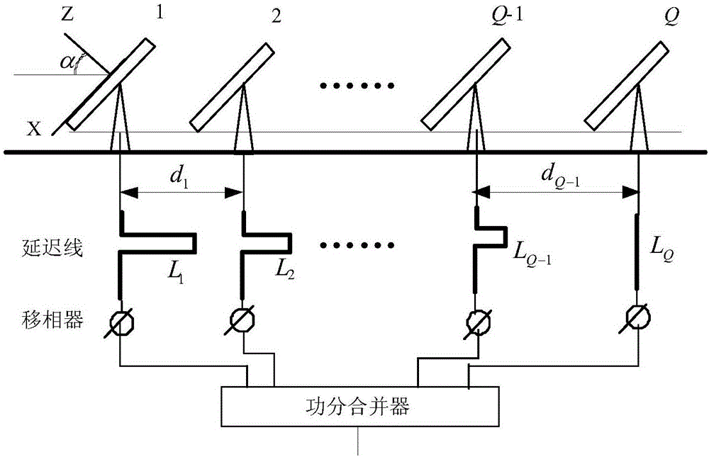
[0035] refer to figure 1 , the multi-subarray antenna beam switching method based on the minimization of delay quantization error of the present invention comprises the following steps:

[0036] 1) Multiple sets of delay lines are used to compensate the phase difference of the multi-subarray antenna, and the scanning range of the multi-subarray antenna is divided into p partitions. For any partition, the last subarray of the partition is used as the phase reference subarray to calculate The delay line length L(n,q) of other sub-arrays in this partition, and establish the delay quantization error model Δl of each sub-array in this partition TTD (n,q), get the maximum time-delay quantization error ΔL of the qth sub-array in the entire scanning range TTD (q);

[0037] 2) Let the total number of delay lines on all sub-arrays be N ALL , where the delay quantization erro...


PUM


Abstract

The present invention discloses a multi-subarray antenna beam switching method based on delay quantization error minimization, comprising the steps of: 1) for a multi-subarray phased array antenna, performing phase compensation using a plurality of delay lines, dividing a scanning range of the antenna into a plurality of subareas, and establishing a maximum delay quantization error model of each subarray in any subarea, to obtain a maximum delay quantization error of each subarray within the whole scanning range; 2) establishing a delay quantization error model of each subarray within the scanning range, establishing an optimization model by taking the number of delay lines as an optimization object and taking the maximum delay quantization error of the multi-subarray antenna as an optimization objective, and solving the optimization model, to obtain the number of delay lines of each subarray; and 3) according to the number of delay lines of each subarray, calculating a scanning range subarea interval corresponding to the subarray and a length of each delay line. According to the method, the phase shift generated when the signal center frequency changes can be compensated by using a plurality of delay lines, thereby implementing the delay quantization error minimization.

Description

technical field [0001] The invention belongs to the technical field of satellite communication system antenna beam control, and relates to a multi-subarray antenna beam switching method based on the minimization of time delay and quantization errors. Background technique [0002] With the progress of the times and the development of science and technology, satellite communication technology has been widely used in the military and civilian fields. Mobile satellite communication technology has become an effective means of broadband mobile communication. Areas such as delivery play an important role. [0003] Multi-subarray technology can effectively reduce the antenna height and system cost, while taking into account the antenna performance, and is currently the most commonly used method for low-profile antennas. In the feeding network of the phased array antenna, the most important phase shifting devices are phase shifters and delay lines, and the phase shift value of the p...

Claims


Application Information

Patent Timeline
IPC IPC(8): H04B7/06H04B7/08H04B7/185
CPCH04B7/0602H04B7/0805H04B7/18578
Inventor 贾维敏姚敏立刘杉金伟戴定成谭志浩
Owner 中国人民解放军火箭军工程大学
Learn More