A debugging method and debugging device for the operating point voltage of a parallel mzi electro-optical modulator

The technology of an electro-optical modulator and a debugging method, which is applied in the field of communication, can solve problems such as difficulty in using and debugging a silicon-optical modulator, and achieve the effects of simple debugging equipment and a fast and efficient adjustment process.

Active Publication Date: 2019-01-22
GUANGXUN SCI & TECH WUHAN
View PDF3 Cites 0 Cited by
  • Summary
  • Abstract
  • Description
  • Claims
  • Application Information

AI Technical Summary

Problems solved by technology

The lithium niobate modulator supplier fujitsu has given the debugging method of the working point voltage of the lithium niobate modulator in its product specification, but this method is not suitable for the working point voltage debugging of the modulator of all materials. For example, silicon-based electro-optic modulators using the thermo-optic effect for biasing
Since the silicon optical modulator is biased by the thermo-optic effect, after the RF signal is input, the RF energy loss generates heat and the voltage of the modulator's operating point changes. It is difficult to use the common method of finding the operating point voltage of the lithium niobate modulator. Debugging the Operating Point Voltage of Silicon Photomodulators

Method used


Image

  • A debugging method and debugging device for the operating point voltage of a parallel mzi electro-optical modulator
  • A debugging method and debugging device for the operating point voltage of a parallel mzi electro-optical modulator
  • A debugging method and debugging device for the operating point voltage of a parallel mzi electro-optical modulator

Examples


Embodiment Construction

[0036] The debugging method of the operating point voltage of the parallel MZI electro-optic modulator in the invention will be described in detail below in combination with the embodiments and the accompanying drawings.

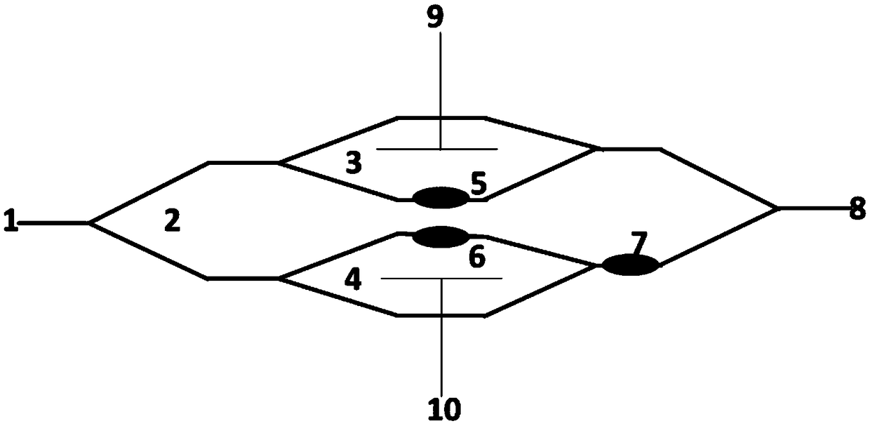
[0037] figure 1It is a schematic diagram of the structure of the parallel MZI electro-optic modulator. The parallel MZI is composed of two sub-MZIs (I channel MZI_3, Q channel MZI_4) in parallel to form a mother MZI_2. The optical paths of I channel MZI_3, Q channel MZI_4 and mother MZI_2 are respectively made with I channels Phase modulation electrode 5, Q path phase modulation electrode 6 and mother MZI phase modulation electrode 7, the radio frequency signal passes through the traveling wave electrode (I path radio frequency electrode) 9, and the traveling wave electrode (Q path radio frequency electrode) 10 is respectively loaded on the I path sub-MZI_3 and On the Q channel MZI_4, the light source enters the parallel MZI structure from the optical input ...


PUM


Abstract

The invention discloses a debugging method and debugging device for the working point voltage of a parallel MZI electro-optic modulator. The bias voltage of one sub-MZI in the sub-MZI; gradually adjust the bias voltage of the other sub-MZI and test the extinction ratio Per of the mother MZI when different bias voltages are applied, and find the extinction ratio Per of the mother MZI when it reaches the minimum value The corresponding bias voltage is used as the operating point voltage of the other sub-MZI; then find the corresponding bias voltage when the extinction ratio Per of the parent MZI reaches the minimum value as the operating point voltage of the sub-MZI; the two sub-MZIs The bias voltages of the MZIs are respectively set to their corresponding operating point voltages, and the phase modulation voltage of the mother MZI is adjusted until the output effect of the parallel MZI electro-optic modulator is optimal, and the phase modulation voltage of the mother MZI is determined. The method and device of the invention are simple, and the adjustment process is quick and efficient.

Description

technical field [0001] The present invention relates to an optical communication device debugging method and its debugging device, in particular to a modulator working point voltage debugging method and its device, in particular to a parallel MZ electro-optical modulator working point voltage debugging method and its device, and the invention belongs to the field of communication. Background technique [0002] In order to realize massive high-speed ultra-long-distance optical data communication, a coherent optical communication system based on optical phase modulation / demodulation has become one of the mainstream solutions. At the transmitting end of coherent optical communication systems, quadrature phase-shift keying (QPSK) electro-optic modulators based on parallel Mach-Zehnder interferometer (MZI) structures have been widely used. A single MZI optical structure divides the input light into two paths, and the two paths of light are combined and interfered after a certain...

Claims


Application Information

Patent Timeline
Patent Type & Authority Patents(China)
IPC IPC(8): H04B10/079
CPCH04B10/0795H04B10/07955G02F1/0123G02F1/21G02F1/212H04B10/5053H04B10/50575G02F1/2255H04B10/079H04B10/548H04B10/556H04B10/564
Inventor 黄钊张博钱坤胡毅马卫东
Owner GUANGXUN SCI & TECH WUHAN
Why Eureka
Try Eureka