
Automatic bias voltage control method and device for parallel mzi type iq electro-optic modulator

An electro-optical modulator and automatic bias technology, which is applied in the field of communication, can solve problems such as bit errors and modulators cannot output high-quality signals, and achieve the effects of simple design, simple debugging equipment, and fast and efficient adjustment process

Active Publication Date: 2019-12-10
GUANGXUN SCI & TECH WUHAN
View PDF5 Cites 0 Cited by
  • Summary
  • Abstract
  • Description
  • Claims
  • Application Information

AI Technical Summary

Problems solved by technology

[0004] For single-polarized parallel MZI-type IQ electro-optic modulators, the operating point voltage will drift due to various factors (environmental changes, device performance changes, etc.) during use, and the modulator cannot output high-quality output after the operating point drifts , the receiving end will generate bit errors after demodulation

Method used


Image

  • Automatic bias voltage control method and device for parallel mzi type iq electro-optic modulator
  • Automatic bias voltage control method and device for parallel mzi type iq electro-optic modulator
  • Automatic bias voltage control method and device for parallel mzi type iq electro-optic modulator

Examples


Embodiment Construction

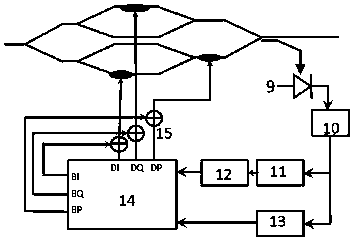
[0036] The automatic bias voltage control method and device of the parallel MZI type IQ electro-optic modulator in the invention will be described in detail below in conjunction with the embodiments and accompanying drawings. In the embodiment, we have adopted a parallel MZI type silicon photonic IQ modulator;

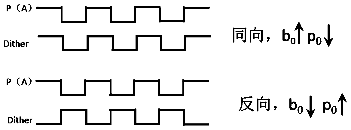
[0037] figure 1 is a schematic diagram of the parallel MZI electro-optic modulator, figure 2It is a block diagram of the automatic bias voltage control of the parallel MZI type IQ electro-optic modulator. The light of the laser enters the IQ modulator from the optical input terminal 1, and then divides it into two equal distributions to the Q channel MZI 2 and the I channel MZI 3. After the radio frequency signal is loaded on the two channels of the MZI, it adjusts the phase modulation electrode 5 of the Q channel and the phase modulation electrode of the I channel. Electrode 6 respectively controls the bias voltage of the two sub-MZIs. When the bias is optimal, the ...


PUM


Abstract

The invention discloses an automatic bias control method and device for a parallel connection MZI type IO electrooptical modulator. The parallel connection MZI type IO electrooptical modulator comprises a main MZI formed through parallel connection of an I-path sub MZI and a Q-path sub MZI, light paths of the I-path sub MZI, the Q-path sub MZI and the main MZI are provided with a Q-path phase modulation electrode, an I-path phase modulation electrode and a pai / 2 phase modulation electrode respectively, and optimal bias voltages of the Q-path phase modulation electrode, the I-path phase modulation electrode and the pai / 2 phase modulation electrode of the parallel connection MZI type IO electrooptical modulator are obtained respectively; disturbance is applied to the Q-path phase modulation electrode, the I-path phase modulation electrode and the pai / 2 phase modulation electrode of the parallel connection MZI type IO electrooptical modulator in sequence, and whether the optimal bias voltages need to be adjusted or not is determined according to average light power feedback of the parallel connection MZI type IO electrooptical modulator. The debugging equipment device is simple, and the debugging process is rapid and efficient.

Description

technical field [0001] The invention relates to an automatic bias voltage control method and device for an electro-optic modulator, in particular to an automatic bias voltage control method and device for a parallel MZ type IQ electro-optic modulator, and the invention belongs to the field of communication. Background technique [0002] In the field of optical fiber communication, larger channel bandwidth, longer transmission distance, and higher receiving sensitivity are always the goals pursued by R&D personnel. The wide use of the existing WDM wavelength division multiplexing system and EDFA optical amplifier has greatly improved the communication capacity and transmission distance of the optical fiber communication system. However, the traditional ASK signal transmission has limited single-channel bandwidth. This traditional optical communication technology is bound to be replaced by more advanced technology. Coherent optical communication technology has begun to attract...

Claims


Application Information

Patent Timeline
Patent Type & Authority Patents(China)
IPC IPC(8): G02F1/03
CPCG02F1/0327
Inventor 黄钊张博钱坤陈宏刚柯威丁兰孙盼胡毅马卫东
Owner GUANGXUN SCI & TECH WUHAN
Learn More