A method and device for is-is protocol cross-level path calculation

A technology of hierarchical path and path calculation request, which is applied in the direction of digital transmission system, data exchange network, electrical components, etc., can solve the problems of high labor cost for configuration and maintenance, error-prone human configuration, and insufficient selection of human configuration, etc., to achieve reduction The effect of staffing costs

Active Publication Date: 2020-01-07
ZTE CORP
View PDF3 Cites 0 Cited by
  • Summary
  • Abstract
  • Description
  • Claims
  • Application Information

AI Technical Summary

Problems solved by technology

[0007] 1. Such tunnel paths in the network are very large, and the loose nodes that meet the conditions are configured one by one, and the labor cost for configuration and maintenance is too high;
[0008] 2. Human configuration is prone to errors;
[0009] 3. When there are multiple routers supporting both level 1 and level 2 at the boundary of level 1 and level 2, human configuration may not select the optimal tunnel path loose node

Method used


Image

  • A method and device for is-is protocol cross-level path calculation
  • A method and device for is-is protocol cross-level path calculation
  • A method and device for is-is protocol cross-level path calculation

Examples


Embodiment 1

[0073] Such as Figure 4 As shown, in the network composed of R1, R2, R3, and R4, R1, R2, and R3 form an area, which is a Level 1 area, and establish a Level 1 neighbor relationship with each other. R2 and R4 establish a Level 2 backbone area, and establish a Level 1 area. 2 neighbors. Obviously, R2 is in the Level 1 area and also in the Level 2 backbone area. The TE router-ids of R1, R2, R3, and R4 intermediate systems are 1.1.1.1, 2.2.2.2, 3.3.3.3, and 4.4.4.4, respectively, which are unique identifiers in the TE network. Obviously, the level 1 function of R1, R2, and R3 ISIS is enabled, and the level 1 function of MPLS is enabled at the same time. R2, the level2 function of R4ISIS is enabled, and the level2 function of MPLS is enabled at the same time. R2 is a router of level 1 / Level 2, and the MPLS function of level 1 / Level 2 is enabled at the same time. Assume that a tunnel is currently configured to calculate the destination from router-id1.1.1.1 to 4.4.4.4, that is,...

Embodiment 2

[0079] Such as Figure 4 , a network composed of R1, R2, R3, and R4. R1, R2, and R3 form an area, which is a Level 1 area, and establish a Level 1 neighbor relationship with each other. R2 and R4 establish a Level 2 backbone area, and establish a Level 2 Neighborhood. Obviously, R2 is in the Level 1 area and also in the Level 2 backbone area. The TErouter-ids of R1, R2, R3, and R4 intermediate systems are 1.1.1.1, 2.2.2.2, 3.3.3.3, and 4.4.4.4, respectively, which are unique identifiers in the TE network. Obviously, the level 1 function of R1, R2, and R3 ISIS is enabled, and the level 1 function of MPLS is enabled at the same time. R2, the level2 function of R4ISIS is enabled, and the level2 function of MPLS is enabled at the same time. R2 is a level 1 / Level 2 router, and the MPLS function of level 1 / Level 2 is enabled at the same time. Assume that a tunnel is currently configured to calculate the destination from router-id 4.4.4.4 to 1.1.1.1, that is, the tunnel from R4 t...


PUM


Abstract

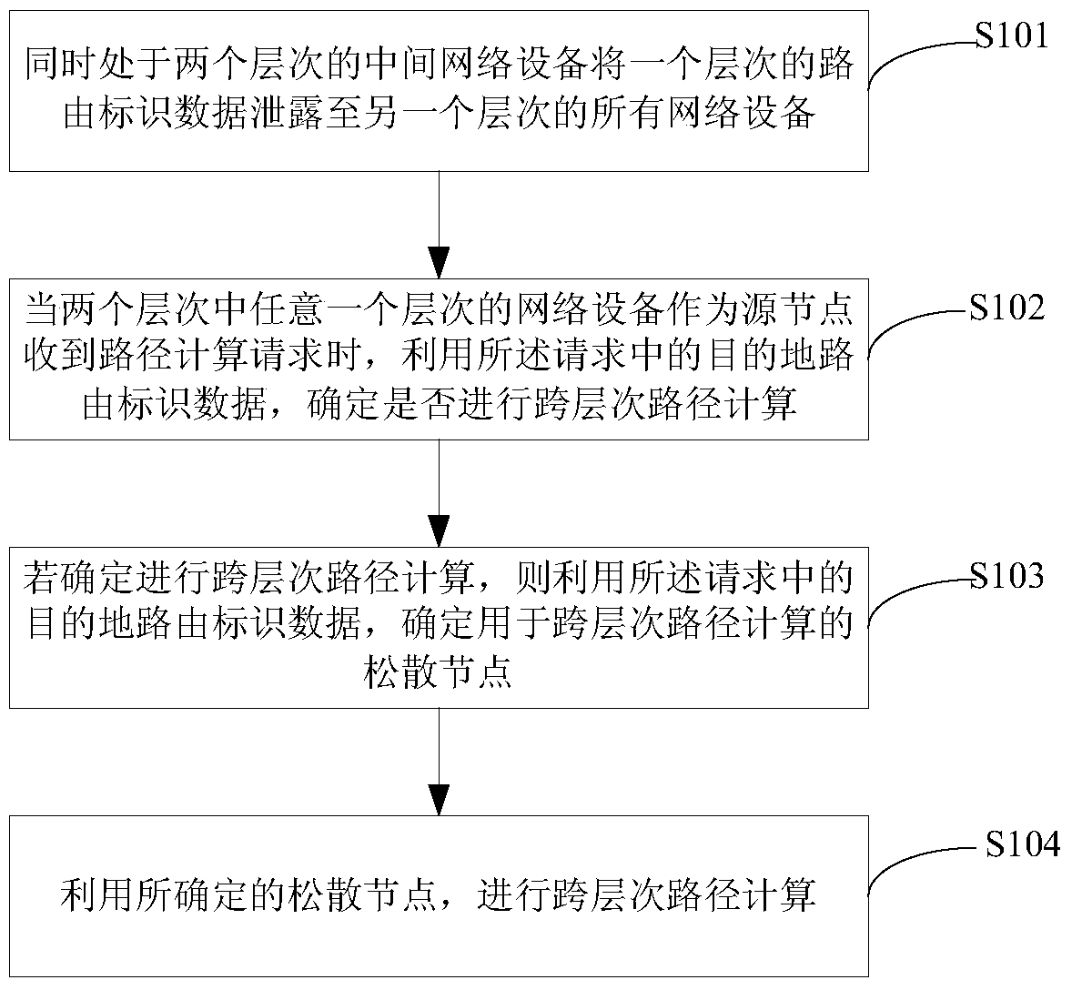
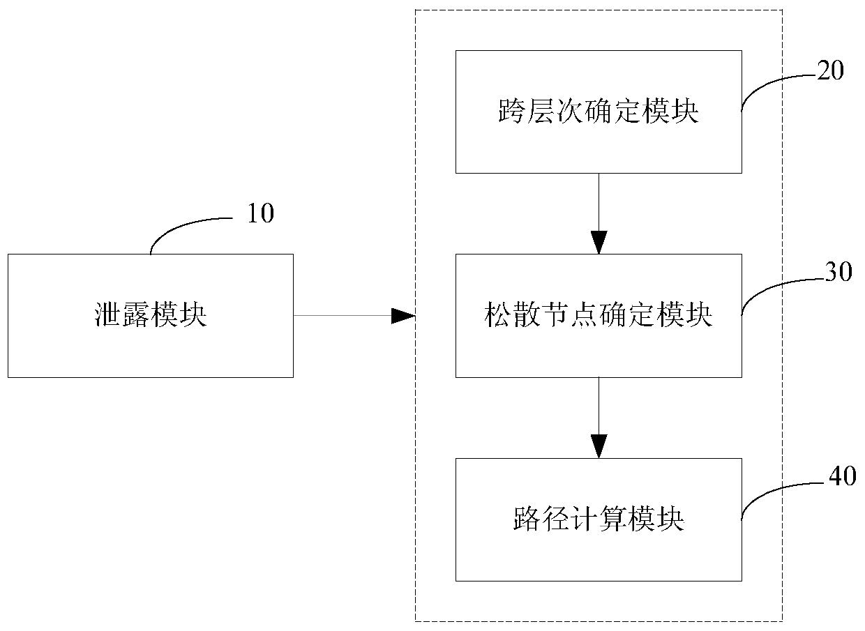
The invention discloses a method and device for calculating an IS-IS protocol cross-level path. The method includes: an intermediate network device at two levels simultaneously leaks routing identification data of one level to all network devices of another level; When a network device at any one of the two levels receives a path calculation request as a source node, use the destination routing identification data in the request to determine whether to perform cross-level path calculation; if it is determined to perform cross-level path calculation, then Using the destination routing identification data in the request, determine the loose nodes used for cross-level path calculation; use the determined loose nodes to perform cross-level path calculation. The present invention eliminates the drawbacks caused by manual configuration and the inability to dynamically adapt to network changes and successfully calculate the cross-level tunnel path, and can calculate the cross-level optimal tunnel path according to the current network state.

Description

technical field [0001] The invention relates to a network device running an intermediate system to intermediate system routing protocol (Intermediate System to Intermediate System, ISIS) routing protocol, in particular to a method and device for ISIS protocol cross-level path calculation. Background technique [0002] ISIS is a dynamic, link state-based Interior Gateway Protocol (Interior Gateway Protocol, IGP). After the ISIS protocol establishes a neighbor through the interactive negotiation of the hello message, each intermediate system (Intermediate System, IS) generates a link-state protocol data packet (Link-State Packet, LSP) to describe the link state information of the IS and sends it to the network , and also store the LSPs sent by all IS devices on the network topology to form a link state database (Link State DataBase, LSDB). In supporting traffic engineering (Traffic Engineer, TE), the LSDB used by ISIS is called traffic engineering link state database (Traffic...

Claims


Application Information

Patent Timeline
Patent Type & Authority Patents(China)
IPC IPC(8): H04L12/715H04L12/751H04L45/02
CPCH04L45/02H04L45/04
Inventor 吴强
Owner ZTE CORP
Why Eureka
Try Eureka