Temperature control system and injection molding machine

A temperature control system and control system technology, applied in the field of temperature control systems and injection molding machines, can solve the problems of complex operation, high production cost of hot runner injection molding hardware, and low precision of hot runner temperature control, so as to reduce staff costs and improve Productivity, quality, and ease of operation for employees

Pending Publication Date: 2022-04-12
SHENZHEN INST OF ADVANCED TECH +1
View PDF0 Cites 0 Cited by
  • Summary
  • Abstract
  • Description
  • Claims
  • Application Information

AI Technical Summary

Problems solved by technology

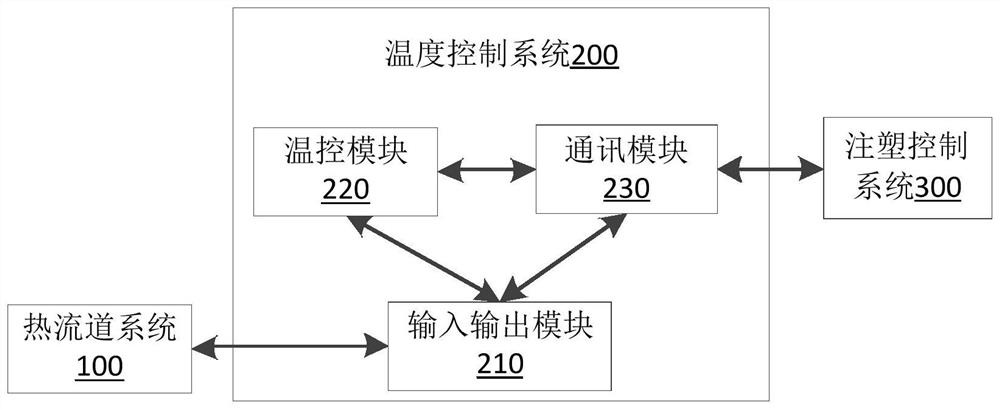
[0002] In the injection molding process of existing hot runner molds, a special hot runner temperature control device is often required to set and control the temperature of the hot runner system separately, and an injection molding control system is also required to control the injection molding process parameters (such as barrel temperature, injection molding temperature, etc.) speed, injection pressure, holding pressure, etc.) to complete the injection molding production of hot runner molds, resulting in high hardware production costs and complicated operations for hot runner injection molding, which is not conducive to injection molding process parameters and hot runner temperature parameters The integrated setting and control of the hot runner, and the temperature control accuracy of the hot runner is not high (generally within ±1-2°C), which affects the quality of injection molding products, etc.

Method used


Image

  • Temperature control system and injection molding machine
  • Temperature control system and injection molding machine
  • Temperature control system and injection molding machine

Examples


Embodiment Construction

[0013] The technical solutions in the embodiments of the present application will be clearly and completely described below in conjunction with the drawings in the embodiments of the present application. It should be understood that the specific embodiments described here are only used to explain the present application, but not to limit the present application. In addition, it should be noted that, for the convenience of description, only some structures related to the present application are shown in the drawings but not all structures. Based on the embodiments in this application, all other embodiments obtained by persons of ordinary skill in the art without making creative efforts belong to the scope of protection of this application.

[0014] Reference herein to an "embodiment" means that a particular feature, structure, or characteristic described in connection with the embodiment can be included in at least one embodiment of the present application. The occurrences of ...


PUM


Abstract

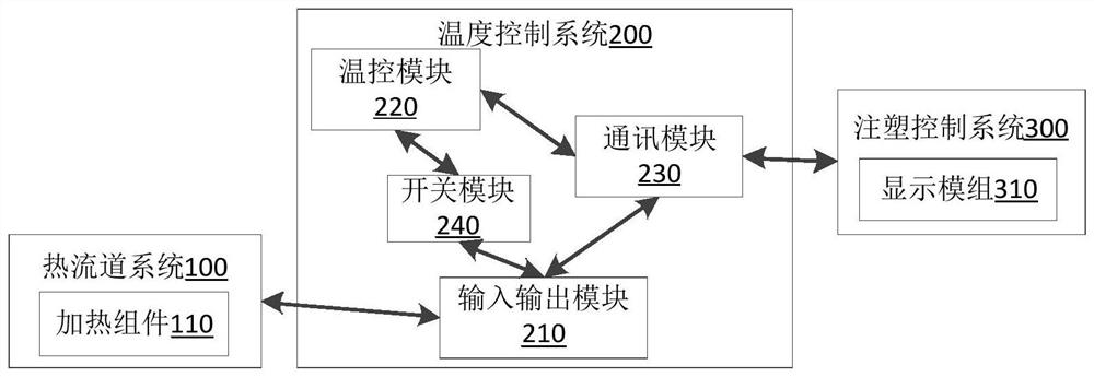
The invention provides a temperature control system and an injection molding machine, the temperature control system is connected with an injection molding control system and a hot runner system of an injection mold so as to control the temperature of the injection mold, and the temperature control system comprises: an input / output module connected with the hot runner system; the temperature control module is connected with the input and output module and is used for acquiring a temperature sensing signal detected by the hot runner system, generating a temperature control signal according to the temperature sensing signal and performing temperature control on the hot runner system according to the temperature control signal; and the communication module is connected with the input and output module, the temperature control module and the injection molding control system, and is used for sending the configuration parameters and / or the state parameters of the hot runner system to the injection molding control system for display, and obtaining a control instruction of the injection molding control system so as to control the hot runner system. By means of the mode, staff operation is facilitated, the staff cost is reduced, and meanwhile the production efficiency and quality of the hot runner mold are improved.

Description

technical field [0001] The present application relates to the field of temperature control, in particular to a temperature control system and an injection molding machine. Background technique [0002] In the injection molding process of existing hot runner molds, a special hot runner temperature control device is often required to set and control the temperature of the hot runner system separately, and an injection molding control system is also required to control the injection molding process parameters (such as barrel temperature, injection molding temperature, etc.) speed, injection pressure, holding pressure, etc.) to complete the injection molding production of hot runner molds, resulting in high hardware production costs and complicated operations for hot runner injection molding, which is not conducive to injection molding process parameters and hot runner temperature parameters The integrated setting and control of the hot runner, and the temperature control accura...

Claims


Application Information

Patent Timeline
IPC IPC(8): B29C45/78B29C45/27
Inventor 冯伟汪智勇于松波潘明华叶俊麟陈俊彬杨金表
Owner SHENZHEN INST OF ADVANCED TECH
Why Eureka
Try Eureka