Eureka AIR delivers breakthrough ideas for toughest innovation challenges, trusted by R&D personnel around the world.

Heat energy circulation baking equipment for electronic components

A technology for electronic components and baking equipment, applied in lighting and heating equipment, drying, drying machines, etc., can solve the problems of low oven space utilization, reduced baking effect, increased oven humidity, etc., to reduce heat Dissipation, saving time to take parts, weakening the effect of air convection

Inactive Publication Date: 2021-04-20
杭州昕华信息科技有限公司
View PDF1 Cites 1 Cited by
  • Summary
  • Abstract
  • Description
  • Claims
  • Application Information

AI Technical Summary

Problems solved by technology

[0006] In order to solve the above technical problems, the present invention provides a heat cycle baking equipment for electronic components to solve the problem of poor air fluidity inside the existing baking equipment, which leads to an increase in the humidity inside the oven after a long time of baking, resulting in a decrease in the baking effect , and when baking different parts, the problem of low utilization of the internal space of the oven is caused by the different sizes and heights of the parts

Method used


Image

  • Heat energy circulation baking equipment for electronic components
  • Heat energy circulation baking equipment for electronic components
  • Heat energy circulation baking equipment for electronic components

Examples


Embodiment

[0031] as attached figure 1 to attach Figure 6 Shown:

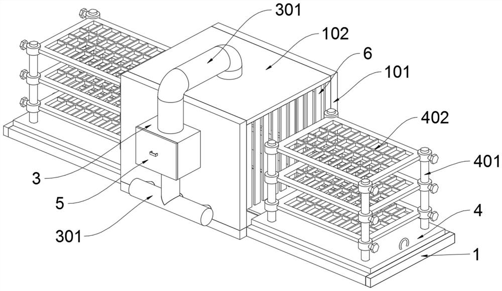
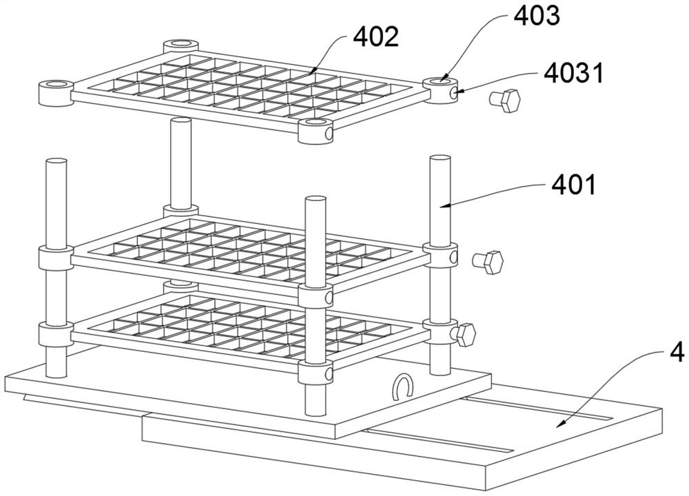
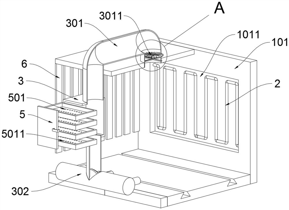
[0032] The present invention provides a heat cycle baking equipment for electronic components, which includes a bottom plate 1 and a sliding plate 4; two sets of track grooves 103 are symmetrically arranged on the upper end surface of the bottom plate 1, and two sets of side rail grooves 103 are symmetrically arranged on the left and right sides of the bottom plate 1. Plate 101, the top of two groups of side plates 101 is fixedly connected with the top plate 102; the upper end of the top plate 102 is provided with a suction pipe 301, and the inside of the suction pipe 301 is provided with a fan 3011; the suction pipe 301 is fixedly connected with the drying box 3, and the drying box 3 The lower end is provided with an air intake pipe 302; the sliding plate 4 is slidingly mounted inside the track groove 103 on the upper surface of the base plate 1; the upper end surface of the sliding plate 4 is symmetrically provided wi...


PUM


Abstract

The invention provides heat energy circulation baking equipment for electronic components. The heat energy circulation baking equipment comprises a bottom plate and a sliding plate. Two groups of rail grooves are symmetrically formed in the upper end face of the bottom plate, two groups of side plates are symmetrically arranged on the left and right sides of the bottom plate, and the top ends of the two groups of side plates are fixedly connected with a top plate. An air suction pipe is arranged at the upper end of the top plate, and a fan is arranged in the air suction pipe. The air suction pipe is fixedly connected with a drying box, and an air inlet pipe is arranged at the lower end of the drying box. The sliding plate is clamped in a rail groove in the upper end face of the bottom plate in a sliding mode. Four fixing rods are symmetrically arranged on the upper end face of the sliding plate, and the fixing rings are connected into the fixing rods in a sleeved mode. According to the heat energy circulation baking equipment, through the arrangement that the outer ends of the fixing rods are sleeved with the fixing rings, the height of a lifting plate can be flexibly adjusted according to the sizes of electronic components, so that the internal space of the baking box can be better utilized, the number of components baked at a time is increased, then fixing bolts penetrate through threaded holes to fasten the fixing rings, the operation is easy, and operation by an employee is facilitated.

Description

technical field [0001] The invention belongs to the technical field of electronic machinery, and more specifically relates to a heat cycle baking equipment for electronic components. Background technique [0002] The baking of electronic components is mainly the baking of IC and BGA integrated circuit components. When the device encounters a high-temperature process after being damp, the moisture in the gaps inside the device will vaporize, and the moisture volume will increase sharply. Cause device expansion, because IC, BGA and other devices are composed of rigid materials, they cannot be restored to their original shape after collision, resulting in internal stress imbalance of the device, which in turn causes cracking, delamination, etc., seriously affecting the quality of the device. [0003] You can refer to the patent application number CN201510570147.9, which discloses a baking device. The baking equipment of the present invention comprises an oven (1), a shutter (2...

Claims


Application Information

Patent Timeline
IPC IPC(8): F26B9/10F26B21/08F26B25/02F26B25/18
Inventor 丁柳朋
Owner 杭州昕华信息科技有限公司
Why Eureka
Eureka Blog
Learn More