High-dynamic-range image synthesis method and device

A high dynamic range, image synthesis technology, used in image communication, TV, color TV components and other directions, can solve the problem of occupying FPGA logic and storage resources

Inactive Publication Date: 2017-01-04
BEIJING LUSTER LIGHTTECH
View PDF3 Cites 14 Cited by
  • Summary
  • Abstract
  • Description
  • Claims
  • Application Information

AI Technical Summary

Problems solved by technology

[0005] This application provides a high dynamic range image synthesis method and device to solve the existi...

Method used


Image

  • High-dynamic-range image synthesis method and device
  • High-dynamic-range image synthesis method and device
  • High-dynamic-range image synthesis method and device

Examples


Embodiment Construction

[0049] Reference will now be made in detail to the exemplary embodiments, examples of which are illustrated in the accompanying drawings. When the following description refers to the accompanying drawings, the same numerals in different drawings refer to the same or similar elements unless otherwise indicated. The implementations described in the following exemplary examples do not represent all implementations consistent with the present invention. Rather, they are merely examples of apparatuses and methods consistent with aspects of the invention as recited in the appended claims.

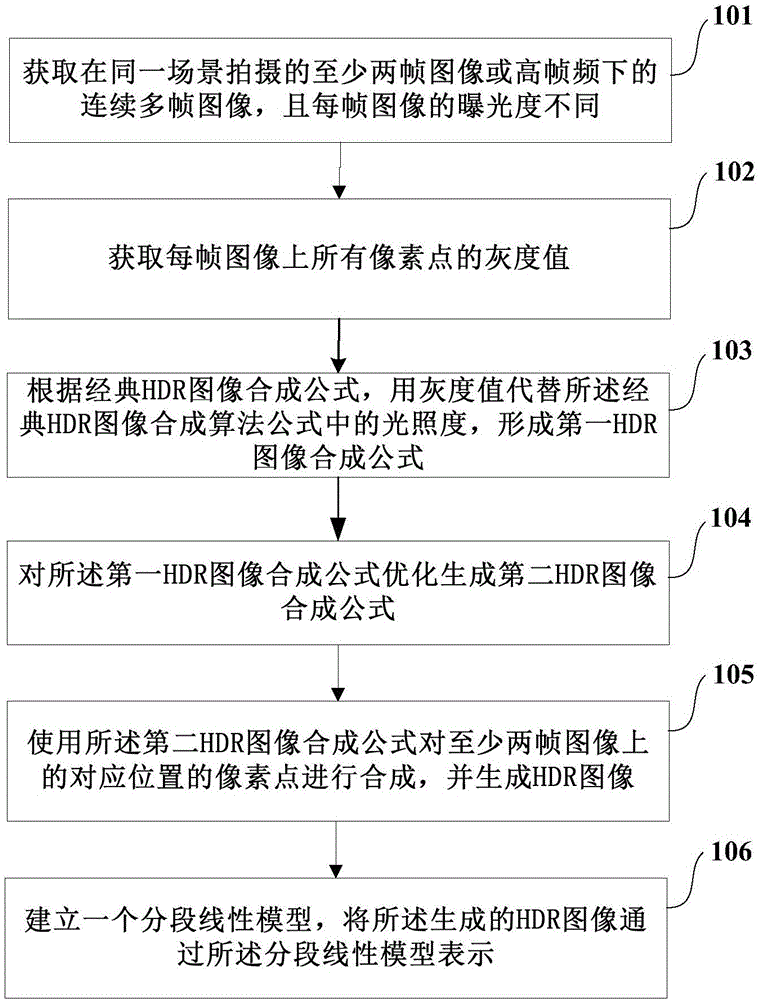
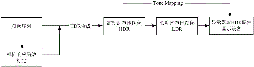
[0050] The embodiment of the present application provides a high dynamic range image synthesis method and device. For black and white images, the image brightness data is a single channel, and this single channel is defined as the Y channel. The HDR image synthesis methods involved in the embodiments of the present application are all in The design is completed on the Y channel. In addition, th...


PUM


Abstract

The invention discloses a high-dynamic-range image synthesis method and device, and the method comprises the steps: obtaining at least two image frames with different exposures or a plurality of image frames at a high frame frequency at the same scene, and obtaining the gray values of all pixels of each image frame; employing the gray values to replace the illuminance according to a classical HDR image synthesis formula, and forming a first HDR image synthesis formula; optimizing the first HDR image synthesis formula, and generating a second HDR image synthesis formula; synthesizing an HDR image through the second HDR image synthesis formula; representing the generated HDR image through a segmented linear model, and enabling the generated HDR image to be displayed on common display equipment. Through simplifying a camera response function and simplifying the HDR image synthesis formula in the HDR synthesis and the optimization process of compression mapping, the method saves a lot of logic and storage resources, thereby improving the implementability of hardware FPGA, and meeting the high-speed and real-time requirements of the hardware equipment.

Description

technical field [0001] The present invention mainly relates to the field of image synthesis, in particular to a high dynamic range image synthesis method and device. Background technique [0002] For a photosensitive element, such as an imaging chip of a camera, the dynamic range (English: Dynamic Range, abbreviation: DR) refers to the range from "darkest" to "brightest" included in the image. The greater the dynamic range, the richer the levels that can be expressed. For a camera, the greater its dynamic range, the richer the details in shadows and highlights it can record at the same time. The real brightness difference in reality, that is, the ratio of the highest object brightness to the darkest object brightness is 10 8 , the brightness range that the human eye can see is 10 5 About, and the brightness range that the general display can represent is only 2 8 (ie 256) different brightness. [0003] With the advancement of technology, cameras with a normal dynamic ra...

Claims


Application Information

Patent Timeline
IPC IPC(8): H04N5/235H04N5/355
CPCH04N23/73H04N25/57
Inventor 杨艺刘淼谢森
Owner BEIJING LUSTER LIGHTTECH
Why Eureka
Try Eureka