Bidirectional lifting fusion cage and rotating mechanism used for driving bidirectional lifting fusion cage

A technology of rotation mechanism and fusion device, applied in medical science, bone implants, prosthesis, etc., can solve problems such as unstable use of vertebral body fusion device, affecting healing success rate, affecting treatment effect, etc.

Active Publication Date: 2017-01-11
GUANGZHOU ARNOLD MEDICAL DEVICE CO LTD
View PDF5 Cites 10 Cited by
  • Summary
  • Abstract
  • Description
  • Claims
  • Application Information

AI Technical Summary

Problems solved by technology

[0002] In daily life, cases of vertebral body damage due to tumors, fractures, infections, etc. occur from time to time. When treating these patients, the current method used is to implant a fusion device between the damaged vertebral bodies to make the bone tissue produce Crawling substitutes to repair the damaged vertebral body. However, the height of the traditional vertebral body fusion cage is fixed, and the height of the intervertebral body of the human body varies from person to person. It is impossible to adjust the height of the vertebral body fusion cage to suit the different needs of different patients. Intervertebral height, so that the vertebral body fusion device cannot be fully adapted to the intervertebral height of the human body, which affects the treatment effect
The general vertebral body fusion device with height adjustment function is not stable when used, and the internal space is small, which may easily cause small space for bone grafting during the operation and affect the healing rate

Method used


Image

  • Bidirectional lifting fusion cage and rotating mechanism used for driving bidirectional lifting fusion cage
  • Bidirectional lifting fusion cage and rotating mechanism used for driving bidirectional lifting fusion cage
  • Bidirectional lifting fusion cage and rotating mechanism used for driving bidirectional lifting fusion cage

Examples


Embodiment Construction

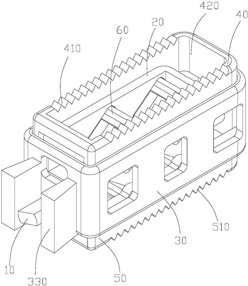
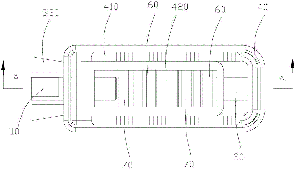
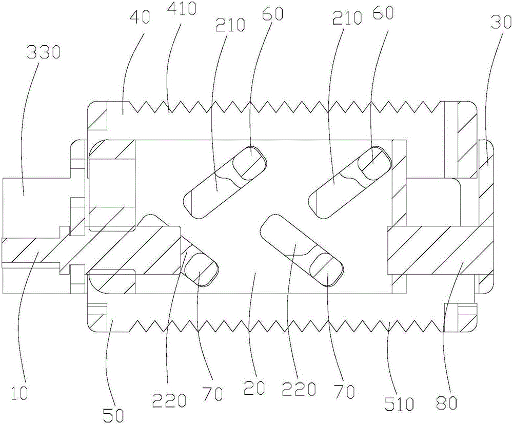
[0034] Such as Figures 1 to 3 As shown, a two-way lifting fusion device includes a screw 10, a middle limiting frame 20, a casing 30, an upper lifting block 40 and a lower lifting block 50, and the casing 30 is sleeved outside the middle limiting frame 20, and The middle limit frame 20 is slidably connected with the shell 30, and one end of the screw 10 passes through the shell 30 and is threadedly connected with one end of the middle limit frame 20, and the upper lifting block 40 is connected with the upper end of the middle limit frame 20. movable socket, the lower lifting block 50 is movable socketed with the lower end of the middle limit frame 20, the two side walls of the middle limit frame 20 are provided with a first chute 210 and a second chute 220, so The inclination directions of the first chute 210 and the second chute 220 are opposite, and the side wall of the upper lifting block 40 is provided with a first latch 60 that is slidably matched with the first chute 21...


PUM


Abstract

The invention relates to a bidirectional lifting fusion cage and a rotating mechanism used for driving bidirectional lifting fusion cage. The bidirectional lifting fusion cage comprises a threaded rod, an intermediate limit box, a shell, an upper lifting block and a lower lifting block, the shell is arranged in a sleeved mode outside the shell and the intermediate limit box is rotatably connected with the shell, one end of the threaded rod is connected to the intermediate limit box with a thread, a first chute and a second chute are formed in both side surfaces of the upper lifting block, slant directions of the first chute and the second chute are opposite, a first bolt matched with the first chute in a slide mode is arranged on the side wall of the upper lifting block, a second bolt matched with the first chute in a slide mode is arranged on the side wall of the lower lifting block. The threaded rod drives the intermediate limit box to move, drives the first bolt to move along the first chute and drives the second bolt to move along the second chute to enable the upper lifting block and the lower lifting block to go up or down, achieving height adjustment; moreover, a larger inner space enables more bone grafting and higher successful healing rate.

Description

technical field [0001] The invention relates to the field of medical equipment, in particular to a two-way elevating fusion device and a rotating mechanism for driving the two-way elevating fusion device. Background technique [0002] In daily life, cases of vertebral body damage due to tumors, fractures, infections, etc. occur from time to time. When treating these patients, the current method used is to implant a fusion device between the damaged vertebral bodies to make the bone tissue produce Crawling substitutes to repair the damaged vertebral body. However, the height of the traditional vertebral body fusion cage is fixed, and the height of the intervertebral body of the human body varies from person to person. It is impossible to adjust the height of the vertebral body fusion cage to suit the different needs of different patients. Intervertebral height, so that the intervertebral height of the human body cannot be fully applied to the vertebral fusion device, which af...

Claims


Application Information

Patent Timeline
Patent Type & Authority Applications(China)
IPC IPC(8): A61F2/44A61F2/46
CPCA61F2/2846A61F2/4455A61F2/4611A61F2002/4687A61F2002/4688
Inventor 赵汝琛成朝福
Owner GUANGZHOU ARNOLD MEDICAL DEVICE CO LTD
Why Eureka
Try Eureka