High-rise building escaper and escaping method

A technology of high-rise buildings and escape devices, which is applied in the field of high-rise building escape devices and escape, and can solve problems such as potential safety hazards, inability to guarantee building power consumption, and limited use of heights

Active Publication Date: 2017-01-11
CHINA CONSTR THIRD ENG BUREAU GRP CO LTD
View PDF4 Cites 6 Cited by
  • Summary
  • Abstract
  • Description
  • Claims
  • Application Information

AI Technical Summary

Problems solved by technology

The biggest problem with these devices is that their use height is limited, no more than 60 meters, and they are not suitable for the escape of high-rise and super high-rise buildings. At the same time, many escape devices require electricity. However, in sudden disasters such as fires and earthquakes, It is often impossible to guarantee the power consumption of the building, so the applicability of the cur

Method used


Image

  • High-rise building escaper and escaping method
  • High-rise building escaper and escaping method
  • High-rise building escaper and escaping method

Examples


Embodiment 1

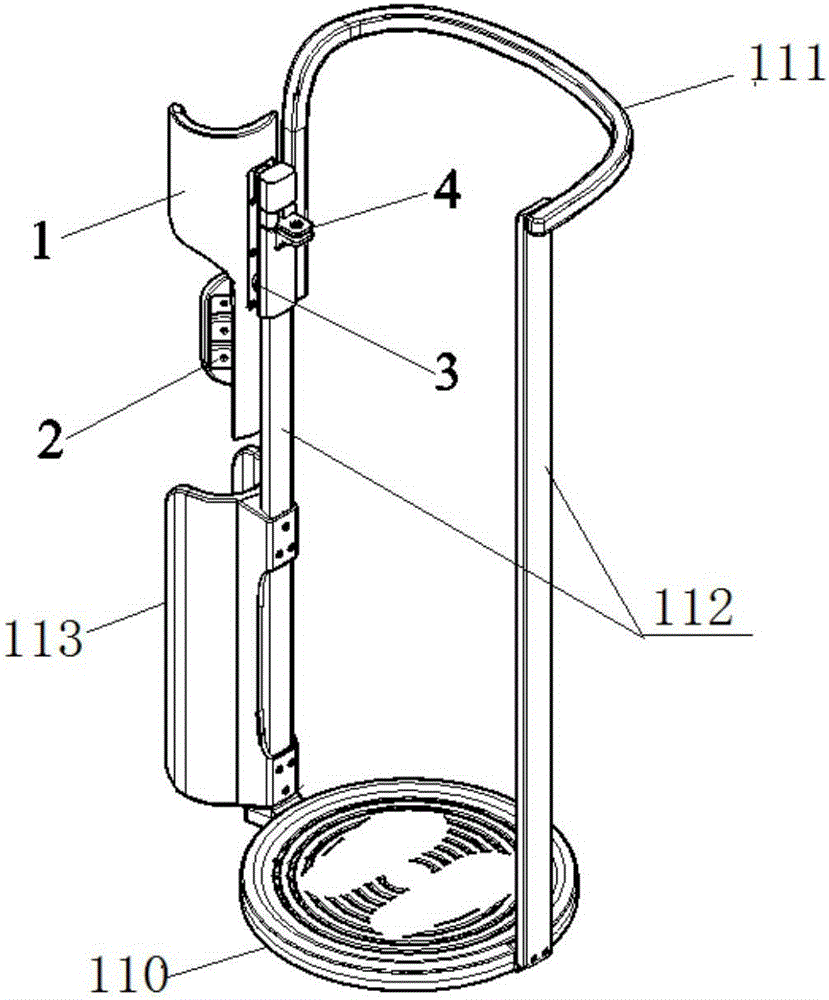
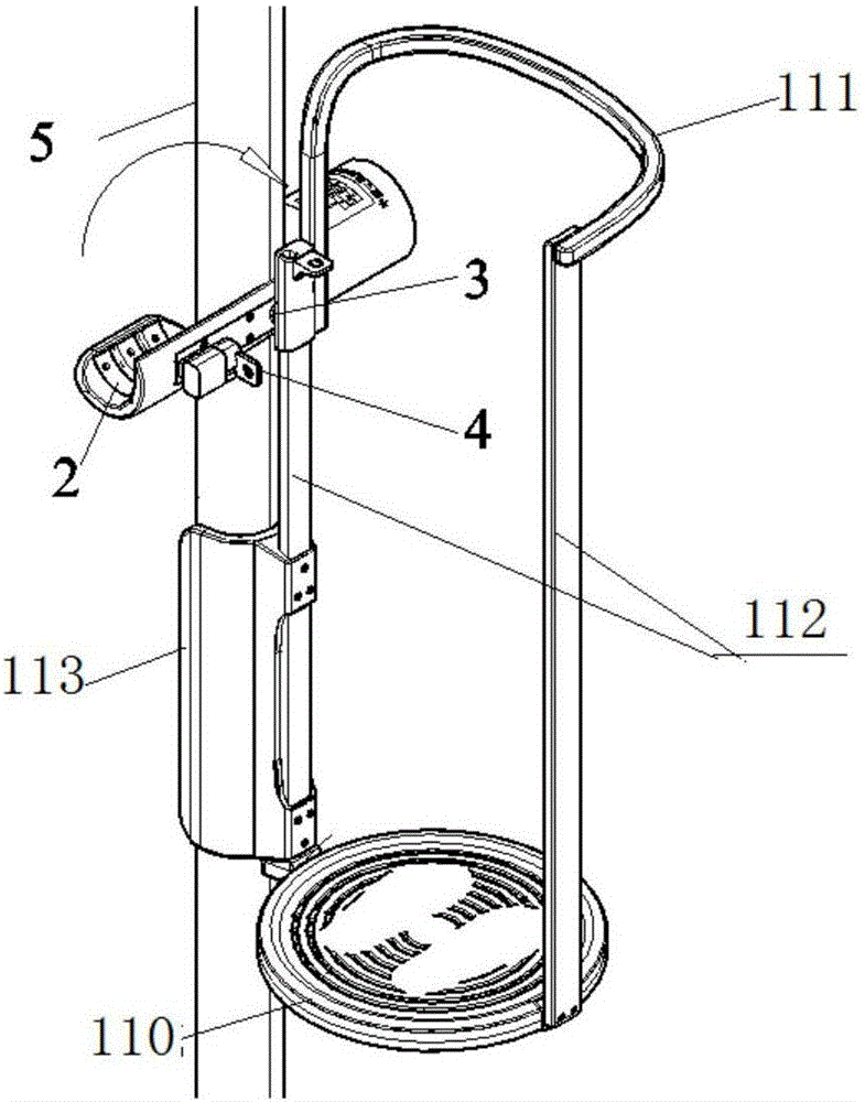
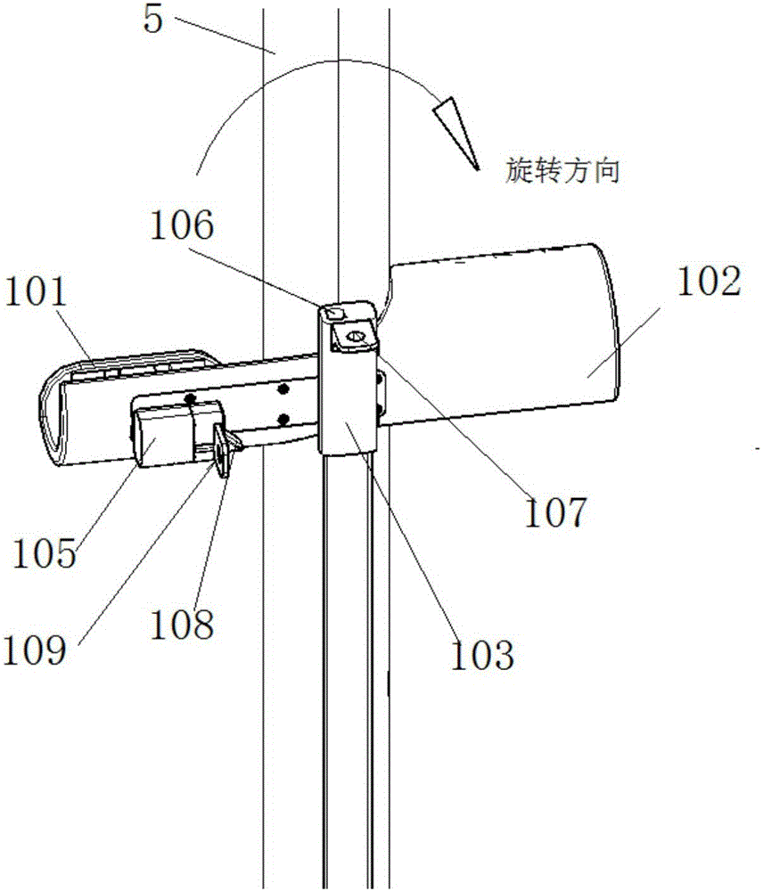
[0066] In a preferred embodiment of the present invention, as Figure 1-Figure 2d As shown, the two arc-shaped tube pieces are the first arc-shaped tube piece 101 and the second arc-shaped tube piece 102 oppositely arranged at both ends of the non-closed sleeve 1, and the first arc-shaped tube piece 101 and the second arc-shaped tube piece 101 are The arc of the cylinder piece 102 is greater than 135° and less than 180°, and the non-closed sleeve 1 is located between the first arc-shaped cylinder piece 101 and the second arc-shaped cylinder piece 102, and an arc-shaped cavity that can accommodate the non-magnetic conductive pipe 5 is provided .

[0067] In a preferred embodiment of the present invention, as Figure 1-Figure 2d As shown, the opening and closing mechanism 3 includes a fixed block 103 fixedly installed on the man-carrying device, and the fixed block 103 is connected to the non-closed sleeve 1 through a rotating shaft 104 .

[0068] In a preferred embodiment of ...

Embodiment 2

[0076] In a preferred embodiment of the present invention, as Figure 3-4b As shown, the two arc-shaped tube pieces are the third arc-shaped tube piece 201 and the fourth arc-shaped tube piece 202 which are reversely hinged through the opening and closing mechanism 3, and the third arc-shaped tube piece 201 and the fourth arc-shaped tube piece 202 can be relatively rotated under the action of the opening and closing mechanism 3 to change the opening of the locking hole.

[0077] In a preferred embodiment of the present invention, as Figure 3-4b As shown, the opening and closing mechanism 3 includes several hinges 203, and the two blades of each hinge 203 are fixedly installed on the third arc-shaped tube piece 201 and the fourth arc-shaped tube piece 202, respectively.

[0078] In a preferred embodiment of the present invention, as Figure 3-4b As shown, the locking mechanism 4 includes a first groove 204 provided at the hinge joint of the third arc-shaped tube piece 201 an...

Embodiment 3

[0085] In a preferred embodiment of the present invention, as Figure 5-6d As shown, the two arc-shaped tube pieces are the fifth arc-shaped tube piece 301 and the sixth arc-shaped tube piece 302 which are reversely hinged through the opening and closing mechanism 3, and the fifth arc-shaped tube piece 301 and the sixth arc-shaped tube piece 302 can be relatively rotated under the action of the opening and closing mechanism 3 to realize the change of the opening of the locking hole. The locking mechanism 4 includes a column 303 vertically arranged between the fifth arc-shaped cylinder piece 301 and the sixth arc-shaped cylinder piece 302 , the third locking block 304 arranged on both sides of the column 303 and the third groove 305 corresponding to the third locking block 304 on the fifth arc-shaped cylinder piece 301 and the sixth arc-shaped cylinder piece 302, when the fifth When the opening of the locking hole formed by the arc-shaped tube piece 301 and the sixth arc-shaped...


PUM

PropertyMeasurementUnit
Radianaaaaaaaaaa
Radianaaaaaaaaaa

Abstract

The invention discloses a high-rise building escaper and an escaping method. The escaper comprises a non-permeability pipeline, a damping device and a person carrying device. The damping device comprises a non-closed sleeve, a high-strength magnet fixedly arranged on the inner wall of the non-closed sleeve, an opening and closing mechanism arranged on the outer wall of the non-closed sleeve, and a locking mechanism. A gap is arranged between the high-strength magnet and the non-permeability pipeline. The non-closed sleeve is provided with a non-closed cylindrical locking hole. The non-closed circle of the locking hole is formed by rolling and folding two arc cylinder sheets in the opposite directions, and the radian of the locking hole is larger than 270 degrees and smaller than 360 degrees. The opening and closing mechanism is used for making the non-closed sleeve arranged on the non-permeability pipeline at any height through the locking hole of the non-closed sleeve in a sleeving manner. The locking mechanism is used for making the locking hole stably arranged in the non-permeability pipeline in a sleeving manner. The applicable height of the high-rise building escaper is not limited, and the high-rise building escaper is suitable for safety escaping in the high-rise building establishing process or the normal operation process.

Description

technical field [0001] The invention belongs to the technical field of building safety protection facilities, and in particular relates to a high-rise building escape device and an escape method, which are suitable for safe escape during the construction or normal operation of high-rise or super high-rise buildings. Background technique [0002] In recent years, high-rise and super high-rise buildings have flourished all over the world, and their construction technology and normal operation and management technology of building structures have been relatively mature. However, in the event of fire and other accidents, there are still major problems in the emergency escape of high-rise and super high-rise buildings. The operating capabilities of fire-fighting facilities and emergency escape facilities are far from meeting people's escape needs. Therefore, the research and development of escape devices for high-rise buildings has extensive practical value. [0003] At present...

Claims


Application Information

Patent Timeline
IPC IPC(8): A62B1/20
Inventor 张琨王辉刘志茂叶智武夏劲松刘彬刘卫军伍勇军付晶晶洪健
Owner CHINA CONSTR THIRD ENG BUREAU GRP CO LTD
Why Eureka
Try Eureka