cleaning device

A technology of cleaning device and cleaning rack, which is applied in the direction of cleaning equipment, cleaning machinery, carpet cleaning, etc., can solve the problems of affecting the use effect, complicated overall operation, and low work efficiency, so as to achieve good use effect, reduce time consumption and improve work efficiency high effect

Active Publication Date: 2021-08-27
浙江爱格家居用品有限公司 +1
View PDF7 Cites 0 Cited by
  • Summary
  • Abstract
  • Description
  • Claims
  • Application Information

AI Technical Summary

Problems solved by technology

However, under this structure, during use, the dehydration operation must be carried out when the bracket is snapped into the upper positioning part by pulling the mop; It can only be carried out by moving with the track to the position where it is locked into the first positioning part. The overall operation is more complicated and the work efficiency is low.
And during dehydration, the bracket is easy to come out from the upper positioning part under the drive of the high rotation of the dehydration part, and derailment occurs, which affects the use effect

Method used


Image

  • cleaning device
  • cleaning device
  • cleaning device

Examples


Embodiment 2

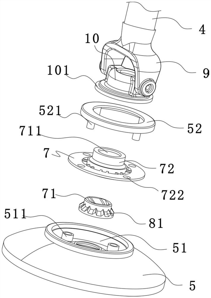
[0074] like Figure 6-10 As shown, the difference between this embodiment and Embodiment 1 is that: a bearing is provided between the connecting piece 72 and the end cover 52; There is a non-rotation matching structure, through which the anti-rotation cooperation between the cleaning basket and the rotating part can be realized, so that when the rotating part rotates, the cleaning basket can be driven to rotate synchronously; through the setting of the anti-rotation matching structure, Realize that the rotating parts can drive the cleaning rack to act together when rotating, and then ensure that the cleaning rack can rotate synchronously with the mop disc, and the dehydration basket will not affect the rotation speed of the mop disc. The mop disc rotates fast and the dehydration effect is good; The anti-rotation matching structure includes a lower anti-rotation piece 30 and an upper anti-rotation piece 40, the lower anti-rotation piece 30 is a tapered convex portion 301 formed...

Embodiment 3

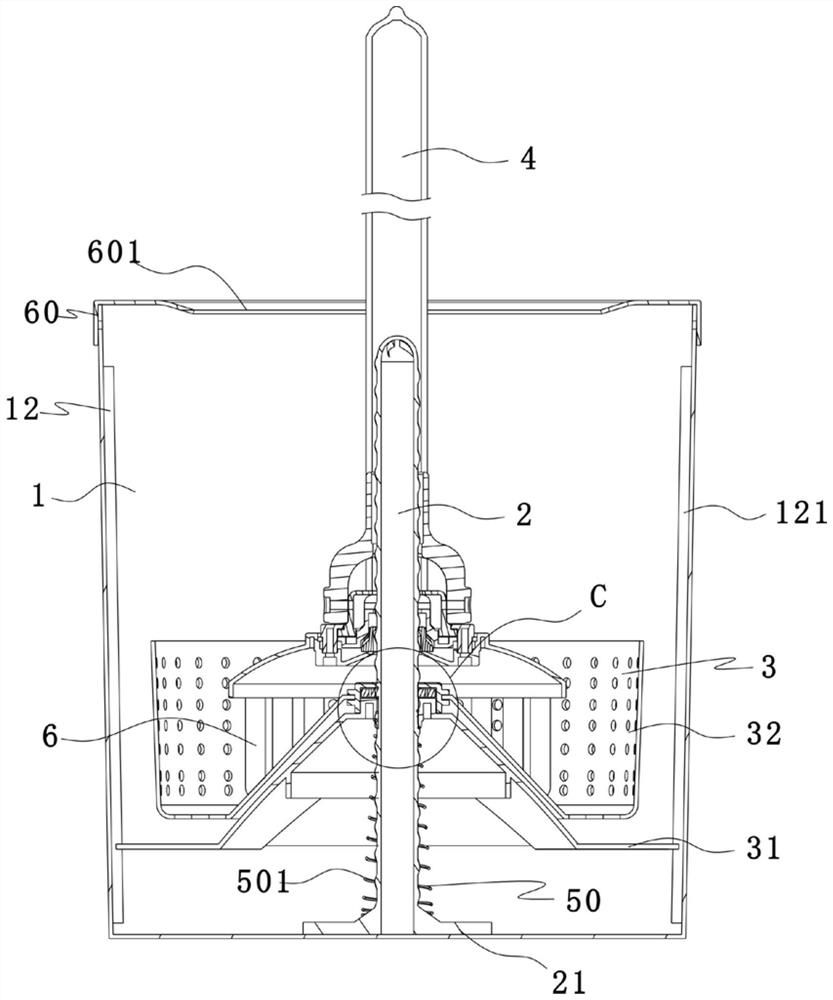
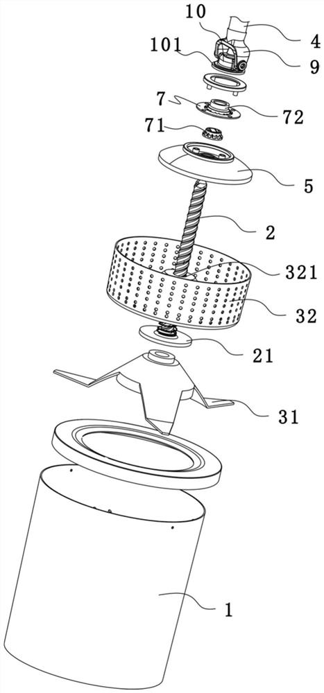
[0078] like Figure 11-17 As shown, a cleaning device includes a mop and a mop barrel matched with the mop. Specifically, the mop includes a rod body 4, a Y-shaped piece 9, a T-shaped joint 10, a mop tray 5, and a mop tray arranged on the mop tray. Mopping, elastic positioning parts and end caps 52, the Y-shaped piece 9 is fixed on the lower part of the rod body 4, the T-shaped joint 10 is hinged with the Y-shaped piece 9, and the T-shaped joint 10 can be generated relative to the mop tray 5 Rotate; the mop bucket includes a barrel body 1, a drive rod 2 located in the barrel body, a cleaning frame 3 located on the drive rod, a driving device and a reset component 50, and the cleaning frame 3 can move up and down along the drive rod 2 and relatively drive The rod 2 rotates; the driving device is used to drive the cleaning rack to rotate in one direction during the downward movement of the cleaning rack 3; the reset component 50 is used to drive the cleaning rack to reset upward...

Embodiment 4

[0089] like Figure 18-25 As shown, a cleaning device includes a mop and a mop bucket matched with the mop. Specifically, the mop bucket includes a bucket body 1, a support rod 2 disposed in the bucket body, and a cleaning frame 3 disposed on the support rod And the reset part 50, the cleaning frame 3 can move up and down along the length direction of the support rod 2, and the reset part 50 is used to drive the cleaning frame upward to reset after the cleaning frame moves down; the support rod 2 is a smooth plastic rod The bottom of the barrel body 1 is arched upwards to form a boss 13, the center of the boss 13 extends downwards to form a cylindrical groove 131, and the support rod is fixedly inserted in the cylindrical groove 131, Thereby realize that support rod is fixedly connected in staving; Described mop comprises rod body 4, Y-shaped piece 9, T-joint 10, mop disc 5, is located on the mopping hair on the mop disc and driving device, specifically, described rod body 4 ...


PUM


Abstract

The invention discloses a cleaning device, which comprises a barrel body; a driving rod, which is arranged in the barrel body, and can move up and down a cleaning frame; a rod body; a mop disc, which can rotate relative to the rod body; The mop disc rotates in one direction; the reset component is used to drive the cleaning rack to reset upwards after the cleaning rack moves down. In the present invention, by setting the driving rod in the bucket body, when the mop is dehydrating, it is only necessary to control the mop to move up and down in the area where the mop plate leaves the water surface, without positioning operation, easy to operate, and high work efficiency; Long-distance up and down movement, labor-saving operation, reduced time-consuming cleaning and dehydration, and improved work efficiency.

Description

technical field [0001] The invention belongs to the technical field of cleaning tools, and in particular relates to a cleaning device. Background technique [0002] Chinese patent CN203749361U discloses a "single bucket type mop bucket", which includes a bucket body, a bracket, a dehydrating part and a guide rail arranged on the bucket body. The guide rail has a lower positioning part and an upper positioning part; the bracket is located in the lower positioning part. when the bracket is on the upper positioning part, it is the dehydration position, and the conversion of the dehydration parts between the cleaning state and the dehydration state is realized by the limit of the guide rail to the bracket. However, under this structure, during use, the dehydration operation must be carried out when the bracket is snapped into the upper positioning part by pulling the mop; It can only be carried out by moving along the track to the position where it is locked into the first posi...

Claims


Application Information

Patent Timeline
Patent Type & Authority Patents(China)
IPC IPC(8): A47L13/58A47L13/20
CPCA47L13/20A47L13/58
Inventor 苏文康
Owner 浙江爱格家居用品有限公司
Why Eureka
Try Eureka