cleaning tools

A technology for cleaning tools and cleaning racks, which can be used in cleaning equipment, cleaning machinery, carpet cleaning, etc.

Active Publication Date: 2021-04-09
浙江爱格家居用品有限公司 +1
View PDF1 Cites 0 Cited by
  • Summary
  • Abstract
  • Description
  • Claims
  • Application Information

AI Technical Summary

Problems solved by technology

But under this kind of structure, in the process of use, the dehydration operation must be carried out when the bracket is snapped into the upper positioning part by pulling the mop; It can only be carried out by moving with the track to the position where it is locked into the first positioning part. The overall operation is complicated and laborious, and the work efficiency is low.
And during dehydration, the bracket is easy to come out from the upper positioning part under the drive of the high rotation of the dehydration part, and derailment occurs, which affects the use effect

Method used


Image

  • cleaning tools
  • cleaning tools
  • cleaning tools

Examples


Embodiment 1

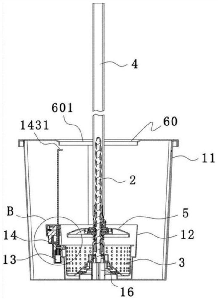
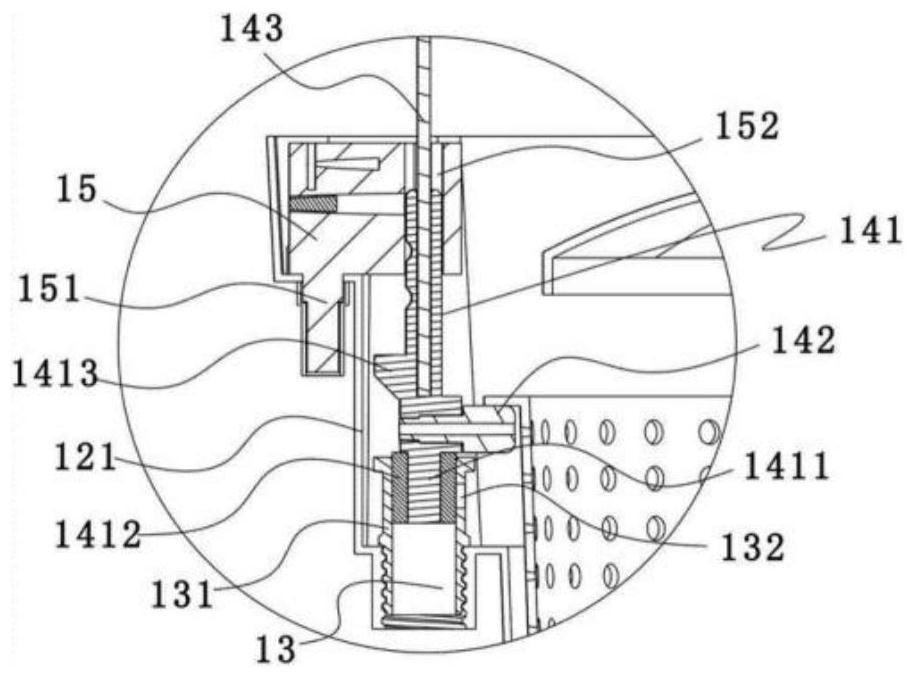
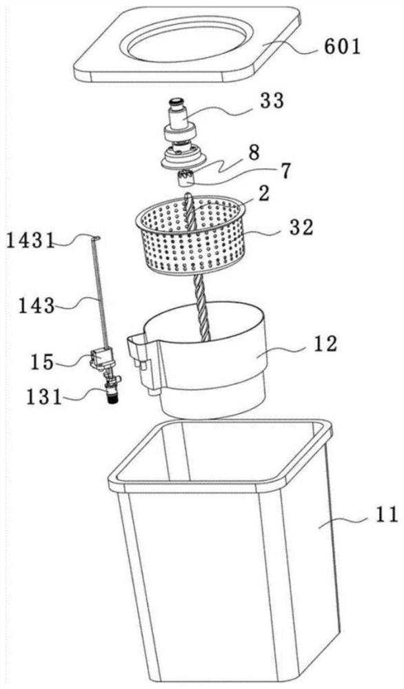
[0070] Such as Figure 1-6 As shown, a cleaning tool includes a mop and a mop bucket matched with the mop. Specifically, the mop bucket includes a bucket body 11, an inner bucket 12 located in the bucket body, a water inlet channel 13, an opening and closing device 14, Drive rod 2, cleaning frame 3 and driving device, the water inlet channel 13 is used to transport the water in the barrel body 11 to the inner barrel, the opening and closing device 14 is used to stop or open the water inlet channel 13, the The mop disc 5 can move up and down along the drive rod 2, and the drive device is used to drive the mop disc 5 to rotate in one direction during the process of pressing down on the rod body; the drive rod 2 is preferably a twist rod made of plastic , the threads on the twist rod 2 can be set to be equidistant, or be set to be dense to sparse, or be set to be sparse to dense, or be set to be dense and alternate, depending on actual usage conditions, without specific limitatio...

Embodiment 2

[0084] Such as Figure 7-11 As shown, a cleaning tool includes a mop and a mop bucket matched with the mop. Specifically, the mop bucket includes a bucket body 11, an inner bucket 12 located in the bucket body, a water inlet channel 13, an opening and closing device 14, Drive rod 2, cleaning rack 3, the water inlet channel 13 is used to transport the water in the barrel body 11 to the inner barrel, the opening and closing device 14 is used to stop or open the water inlet channel 13, and the The driving rod 2 moves up and down; the driving rod 2 is preferably a twist rod made of plastic, and the threads on the twist rod 2 can be set to be equidistant, or can be set from dense to sparse, or from sparse to dense. , or set to alternate density, according to the actual use, not specifically limited; the drive rod 2 includes an outer rod 22 and an inner rod 23 pierced in the outer rod, and the outer rod 22 is made of plastic The inner rod 23 is preferably made of metal; the bottom ...

Embodiment 3

[0097] Such as Figure 12-18 As shown, a cleaning tool that is convenient to use includes a mop and a mop bucket matched with the mop. Specifically, the mop bucket includes a bucket body 11, an inner bucket 12 located in the bucket body, a water inlet channel 13, an opening and closing Device 14, drive rod 2, cleaning frame 3, the water inlet channel 13 is used to transport the water in the barrel body 11 to the inner barrel, the opening and closing device 14 is used to stop or open the water inlet channel 13, the It can move up and down along the drive rod 2; the drive rod 2 is preferably a plastic rod; the bottom of the inner barrel 12 is arched upwards to form a boss 16, and the center of the boss 16 extends downward to form a cylindrical concave groove, and the outer rod 22 is fixedly passed through the cylindrical groove, so as to realize the fixed connection of the drive rod in the inner barrel.

[0098]The mop includes a rod body 4, a Y-shaped piece 9, a T-joint 10, a ...


PUM


Abstract

The invention discloses a cleaning tool, which comprises a rod body; a mop disc, which can rotate relative to the rod body; a barrel body; an inner barrel, which is arranged in the barrel body; a water inlet channel, which is used to transport the water in the barrel body to the inner barrel; Or open the water inlet channel; a driving rod; a cleaning rack that can move up and down along the driving rod; a driving device that drives the mop disc to rotate in one direction during the process of pressing down the rod body. In the present invention, by setting the driving rod on the mop bucket and setting the mop bucket as an inner and outer bucket structure, and then directly controlling the up and down movement of the mop, the cleaning and dehydration operations of the mop can be realized without positioning operation, the operation is simple and labor-saving, and the work efficiency is high; Secondly, because there is no need for positioning, there will be no derailment, the failure rate is low, and the use effect is good; and there is no need to control the mop to move up and down for a long distance, and the operation is labor-saving.

Description

technical field [0001] The invention belongs to the technical field of cleaning tools, in particular to a cleaning tool. Background technique [0002] Chinese patent CN203749361U discloses a "single bucket type mop bucket", which includes a bucket body, a bracket, a dehydrating part and a guide rail arranged on the bucket body. The guide rail has a lower positioning part and an upper positioning part; the bracket is located in the lower positioning part. when the bracket is on the upper positioning part, it is the dehydration position, and the conversion of the dehydration parts between the cleaning state and the dehydration state is realized by the limit of the guide rail to the bracket. However, under this structure, during use, the dehydration operation must be carried out when the bracket is snapped into the upper positioning part by pulling the mop; It can only be carried out by moving along the track to the position where it is locked into the first positioning part. ...

Claims


Application Information

Patent Timeline
Patent Type & Authority Patents(China)
IPC IPC(8): A47L13/59
CPCA47L13/59
Inventor 苏文康
Owner 浙江爱格家居用品有限公司
Why Eureka
Try Eureka