
A tubular injection molding die, production device and production process

A technology for producing devices and forming molds, which can be applied to tubular items, household appliances, other household appliances, etc., and can solve the problems of low collection efficiency and low safety factor.

Active Publication Date: 2018-12-04
JIANGYIN HOMEN RUBBER PLASTIC PROD
View PDF7 Cites 0 Cited by
  • Summary
  • Abstract
  • Description
  • Claims
  • Application Information

AI Technical Summary

Problems solved by technology

In the prior art, the molds for producing the above-mentioned injection parts mostly include upper template, lower template and needle inserts. The products obtained after molding are connected by latex sheets, which need to be imported into cutting equipment for punching, and the injection parts need to be cut manually. If it is removed from the mold of the equipment, the collection efficiency is low, and the operator puts his hands under the punching equipment, so the safety factor is low

Method used


Image

  • A tubular injection molding die, production device and production process
  • A tubular injection molding die, production device and production process
  • A tubular injection molding die, production device and production process

Examples


Embodiment 1

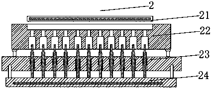
[0032] Such as figure 1 As shown, the tubular injection molding mold 2 of Embodiment 1 includes an upper template 21, a first middle template 22, a second middle template 23 and a lower template 24 from top to bottom, and a heating Mechanism 5; the top surface of the first middle template 22 is provided with a recessed part 6 that matches the bottom surface of the upper template 21, and the first middle template 22 and the second middle template 23 below the recessed part 6 are provided with a one-to-one corresponding rubber flow Road through holes 7, the lower template 24 is provided with insert pins 8 corresponding to the rubber flow channel through holes one by one. The setting pin 8 is a variable diameter setting pin.

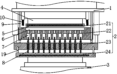
[0033] Such as figure 2 As shown, the tubular injection part production device in embodiment 1 includes an upper mold base 1, a forming mold 2 and a lower mold base 3, and the upper mold plate 21 and the upper mold base 1, the lower mold plate 24 and the...

Embodiment 2

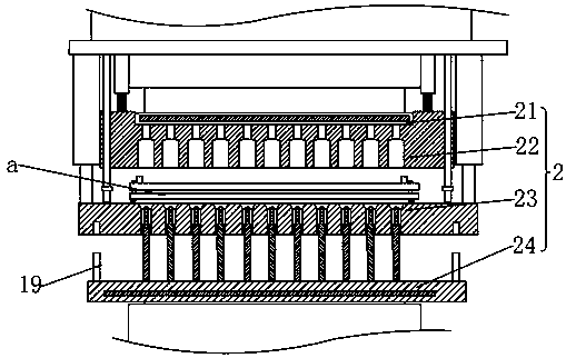
[0037] Such as Figure 3-5 As shown, the difference between embodiment 2 and embodiment 1 is that the production device of embodiment 2 also includes a clamping mechanism a, and the clamping mechanism includes a first orifice plate 11 and a second orifice plate 12, and the first orifice plate 11 and the second orifice plate The matching holes of the injection parts on the second orifice plate 12 are provided in one-to-one correspondence, and the surface of the second orifice plate 12 is provided with vertical bosses, which are connected with the strip holes 13 on the first orifice plate 11 in clearance fit, and the bosses A stop nut 14 is arranged at the free end of the first orifice plate 11 and a micro-motion mechanism is arranged between the first orifice plate 11 and the second orifice plate 12, and the micro-motion mechanism drives the first orifice plate to move along the long side direction of the strip hole.

[0038] In Embodiment 2, the micro-motion mechanism includes...

Embodiment 3

[0040] Such as Figure 6 As shown, the difference between embodiment 3 and embodiment 2 is that the micro-motion mechanism is a linear cylinder 18 that is axially consistent with the long side of the strip hole, the piston of the linear cylinder 18 is fixedly connected with the first orifice plate, and the cylinder of the linear cylinder 18 The body is fixedly connected with the second orifice plate.

[0041] In order to maintain the balance of the clamping mechanism, the micro-motion cylinder can be arranged symmetrically. Micro cylinders can be used in actual use.

[0042]The diameter of the rubber runner through hole on the top surface of the second middle template 23 is larger than the diameter of the rubber runner through hole 7 on the bottom surface of the second middle template 23 .

[0043] Before molding, first spray silicone oil on the top depression of the first middle template and the surface of the insert pin, then place the raw material in the top depression of...


PUM


Abstract

The invention discloses a tubular injection piece mold. The mold sequentially comprises an upper mold plate, a first middle mold plate, a second middle mold plate and a lower mold plate from top to bottom, wherein heating mechanisms are arranged in the upper mold plate and the lower mold plate; the top surface of the first middle mold plate is provided with a depressed part matched with the bottom surface of the upper mold plate; rubber flow channel through holes in one-to-one correspondence are arranged in the first middle mold plate and the second middle mold plate below the depressed part; and pins which are in one-to-one correspondence with the rubber flow channel through holes are protruded on the lower mold plate. Since the tubular injection piece mold is composed of the upper mold plate, the first middle mold plate, the second middle mold plate and the lower mold plate, the remaining latex in the depressed part of the first middle mold plate after mold pressing is spread in the depressed part, and the remaining latex on the lower mold plate is punctured between the pins, so that the remaining latex can be quickly stripped, and the injection piece finished product can be prepared in one step, thus achieving high production efficiency. The invention also discloses a production device containing the tubular injection piece mold and a corresponding production process.

Description

technical field [0001] The invention relates to the technical field of production equipment for medical injection parts, in particular to a molding die for tubular injection parts, a production device and a production process. Background technique [0002] In the commonly used infusion device structure, a section of latex bubble tube is connected to the infusion tube on the side of the needle, also known as latex injection parts. The outer diameter of the connecting section at both ends of the injection part is smaller than that of the middle part. The through hole is usually a through hole with a reduced diameter, which can reduce the amount of raw material used for a single injection part. In the prior art, the molds for producing the above-mentioned injection parts mostly include upper template, lower template and needle inserts. The products obtained after molding are connected by latex sheets, which need to be imported into cutting equipment for punching, and the inject...

Claims


Application Information

Patent Timeline
Patent Type & Authority Patents(China)
IPC IPC(8): B29C45/26B29C45/73B29C45/42B29L23/00
CPCB29C45/2606B29C45/42B29C45/4225B29C45/73B29L2023/007
Inventor 吴红清
Owner JIANGYIN HOMEN RUBBER PLASTIC PROD
Features
  • Generate Ideas
  • Intellectual Property
  • Life Sciences
  • Materials
  • Tech Scout
  • Unparalleled Data Quality
  • Higher Quality Content
  • 60% Fewer Hallucinations
Learn More