HVAC assembly

An assembly and chamber technology, applied in the field of automotive air conditioners, can solve problems such as large volume, and achieve the effects of reducing space volume, increasing the scope of application, and reducing weight

Inactive Publication Date: 2017-01-11
芜湖德鑫汽车空调有限公司
View PDF6 Cites 2 Cited by
  • Summary
  • Abstract
  • Description
  • Claims
  • Application Information

AI Technical Summary

Problems solved by technology

[0004] Existing automotive air conditioners include a blower housing, an evaporator housing, and a heater housing. The

Method used


Image

  • HVAC assembly

Examples


Embodiment Construction

[0021] Specific embodiments of the present invention will be described in detail below in conjunction with the accompanying drawings. It should be understood that the specific embodiments described here are only used to illustrate and explain the present invention, and are not intended to limit the present invention.

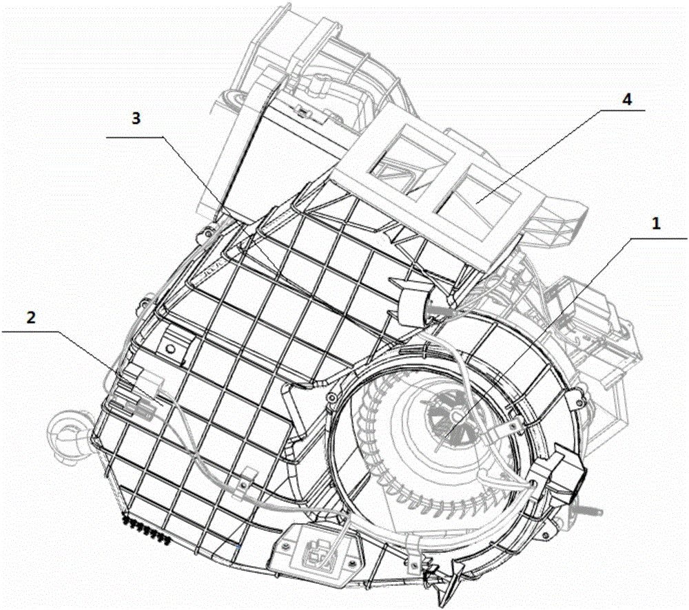
[0022] In the present invention, unless stated otherwise, the used orientation words such as "up, down, left, right" usually refer to figure 1 Up and down and left and right are shown. "Inner and outer" refer to the inner and outer on the specific outline. "Far and near" refer to far and near relative to a certain component.

[0023] The present invention provides a kind of HVAC assembly, and this HVAC assembly comprises: blower, evaporator, heater, blower chamber 1, evaporator chamber 2 and heater chamber 3; Wherein, described blower chamber 1, evaporator The heater chamber 2 and the heater chamber 3 are streamlined and communicated in sequence; the side of ...


PUM


Abstract

The invention discloses a HVAC assembly which comprises a blower, an evaporator, a heater, a blower chamber (1),an evaporator chamber (2) and a heater chamber (3); the blower chamber (1), the evaporator chamber(2) and the heater chamber (3) are streamlined and communicated in sequence; an air outlet (4) is formed in one side, away from the evaporator chamber (2),of the heater chamber (3); the blower, the evaporator and the heater are arranged in the blower chamber (1), the evaporator chamber (2) and heater chamber (3) correspondingly one to one. The HVAC assembly solves the problem that the HVAC assembly is oversized in the prior art, and realizes striction of the HVAC assembly.

Description

technical field [0001] The present invention relates to automotive air conditioners and, in particular, to HVAC assemblies. Background technique [0002] The car air conditioner is composed of compressor, condenser, throttling element, evaporator, fan and necessary control components, and is used to adjust the temperature and humidity in the car and provide a comfortable air conditioning system for the occupants. [0003] When the compressor is working, the compressor sucks the low-temperature and low-pressure gaseous refrigerant from the evaporator, after compression, the temperature and pressure of the refrigerant rise, and then it is sent into the condenser. In the condenser, the high-temperature and high-pressure gaseous refrigerant transfers heat to the outside air passing through the condenser to be liquefied and become a liquid. When the liquid refrigerant flows through the throttling device, the temperature and pressure decrease and enter the evaporator. In the eva...

Claims


Application Information

Patent Timeline
IPC IPC(8): B60H1/00
CPCB60H1/00021B60H2001/00078
Inventor 李茂勇陈天祥
Owner 芜湖德鑫汽车空调有限公司
Why Eureka
Try Eureka