Catapulting rollout device and catapulting system of unmanned aerial vehicle

A technology of unmanned aerial vehicle and sliding, which is applied in the direction of launching/dragging transmission device, etc. It can solve the problems of damage to the structure of the ejection frame, poor connection method, and damage to the structure of the drone, so as to avoid direct contact, durable use, and use stable effect

Active Publication Date: 2017-01-11
北京韦加智能科技股份有限公司
View PDF8 Cites 10 Cited by
  • Summary
  • Abstract
  • Description
  • Claims
  • Application Information

AI Technical Summary

Problems solved by technology

[0003] At present, many ejection methods are direct contact between the aircraft and the ejection rack device. The contact position is the bearing point of the aircraft itself or the redundant structure extended by the drone as the force point of the ejection, which has a certain impact on the structure and life of the aircraft. , especially for heavy drones, the connection between the connection structure and the ejection frame, and the connection between the connection structure and the aircraft are not handled well, which can easily lead to damage to the structure of the drone and the structure of the ejection frame.

Method used


Image

  • Catapulting rollout device and catapulting system of unmanned aerial vehicle
  • Catapulting rollout device and catapulting system of unmanned aerial vehicle
  • Catapulting rollout device and catapulting system of unmanned aerial vehicle

Examples


Embodiment 1

[0037] The UAV ejection and sliding device provided in this embodiment is arranged on the ejection frame for carrying the UAV and ejecting the UAV. The sliding frame for carrying the UAV and the pulley arranged at the bottom end of the sliding frame, the locking mechanism is arranged at the end of the sliding frame close to the initial end of the ejection frame, and is used to place the drone The man-machine is locked at the initial end of the ejection frame.

[0038] In the prior art, since the UAV is in direct contact with the ejection frame, the contact position is the bearing point of the UAV itself or the redundant structure extended from the UAV is used as the force point of the ejection, which has a certain impact on the structure and life of the aircraft. Impact, easily lead to the loss of the structure of the UAV and the structure of the ejection frame and other issues. The UAV ejection and sliding device provided in this embodiment, by setting the sliding frame on t...

Embodiment 2

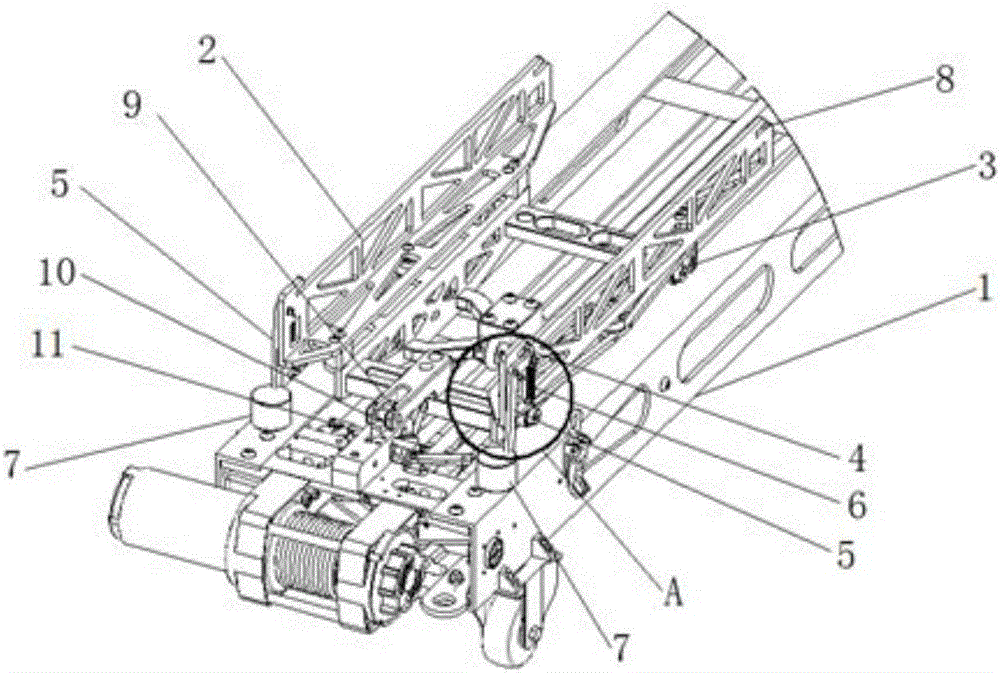
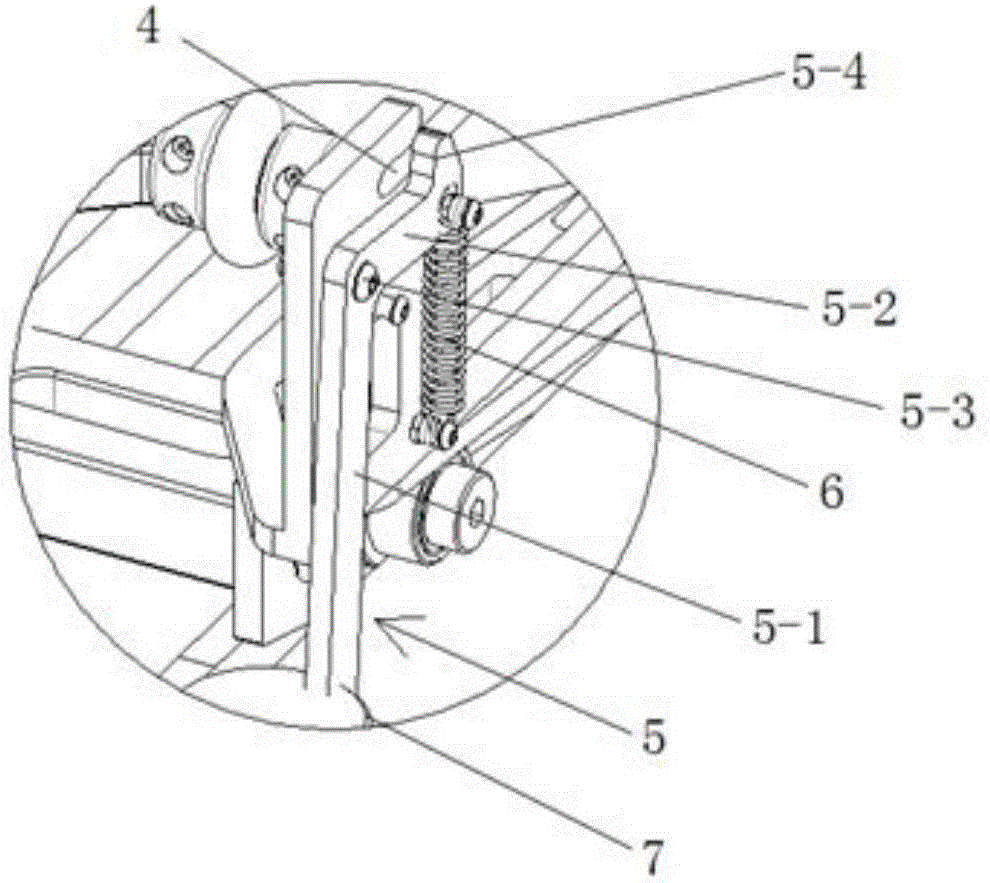
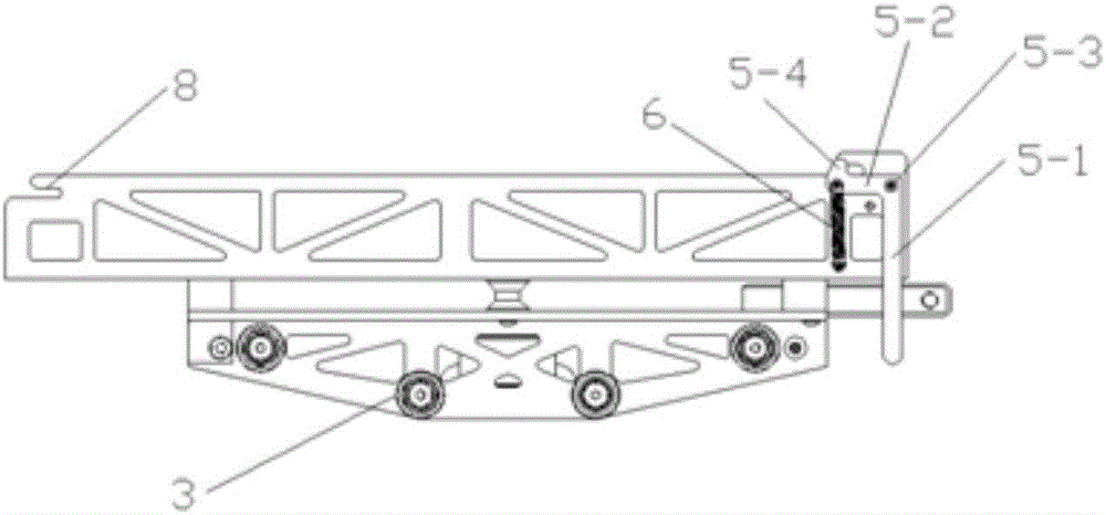
[0040] Such as Figures 1 to 3 As shown, the UAV ejection and sliding device provided in this embodiment is arranged on the ejection frame 1 for carrying the UAV and ejecting the UAV. It includes a locking mechanism and is arranged on the ejection frame 1 The sliding frame 2 for carrying the drone on the sliding track and the pulley 3 arranged at the bottom of the sliding frame 2, the locking mechanism is arranged on the sliding frame 2 near the ejection frame 1 One end of the initial end is used for locking the drone on the initial end of the ejection rack 1 .

[0041] The locking mechanism includes a first card slot 4 and a first limit member, the opening direction of the first card slot 4 is consistent with the moving direction of the sliding frame 2, and is used to accommodate the The first fixing part at the bottom; when the sliding frame 2 is located at the initial end of the ejection frame 1, the first limiting member covers the opening of the first card slot 4 to limi...

Embodiment 3

[0048] Such as Figures 4 to 7 As shown, this embodiment provides a UAV ejection system, which includes a drive mechanism, an ejection frame, and the UAV ejection and sliding device described in Embodiment 1 or Embodiment 2 provided on the ejection frame. 12. Steel wire rope 15, rubber band, connecting rope, anti-collision rope 13, first metal plate and second metal plate; one end of the steel wire rope 15 is connected with the drive mechanism 14 arranged at the initial end of the ejection frame, and the other end is connected with the The first metal plate is connected, the first metal plate is slidingly connected with the ejection frame 1, and is located between the sliding frame 2 and the end of the ejection frame 1; the second metal plate is connected with the ejection frame 1 The ejection frame 1 is slidably connected and located between the first metal plate and the end of the ejection frame 1, the rubber band is arranged between the first metal plate and the second meta...


PUM


Abstract

The invention relates to a catapulting rollout device and a catapulting system of an unmanned aerial vehicle. The catapulting rollout device of the unmanned aerial vehicle is arranged on a catapulting frame and used for bearing the unmanned aerial vehicle and catapulting the unmanned aerial vehicle. The catapulting rollout device comprises a locking mechanism, a rollout frame arranged on a sliding track of the catapulting frame and used for bearing the unmanned aerial vehicle and sliding wheels arranged at the bottom ends of the rollout frame, wherein the locking mechanism is arranged at the end, close to the initial end of the catapulting frame, of the rollout frame and used for locking the unmanned aerial vehicle at the initial end of the catapulting frame and can ensure that the rollout frame slides on the sliding track and accordingly drives the unmanned aerial vehicle on the rollout frame to slide. Direct contact between the unmanned aerial vehicle and the catapulting frame is avoided, it is ensured that the catapulting frame structure is not damaged due to catapulting, and the catapulting rollout device is durable and stable to use and can catapult the unmanned aerial vehicle in a long-time and high-efficiency mode.

Description

technical field [0001] The invention relates to the technical field of unmanned aerial vehicle take-off, in particular to an unmanned aerial vehicle ejection sliding device and an ejection system. Background technique [0002] At present, there are many ways to take off UAVs. For UAVs that can operate for a long time, most of them are beyond the scope of micro-UAVs in size and weight, and most of the take-off methods are sliding and ejection. Ejection is obviously a safer and more practical way to take off, which can reduce the difficulty of flying and is not limited by the take-off site. [0003] At present, many ejection methods are direct contact between the aircraft and the ejection rack device. The contact position is the bearing point of the aircraft itself or the redundant structure extended by the drone as the force point of the ejection, which has a certain impact on the structure and life of the aircraft. , especially for heavy drones, the connection between the c...

Claims


Application Information

Patent Timeline
Patent Type & Authority Applications(China)
IPC IPC(8): B64F1/06
CPCB64F1/06B64U70/70
Inventor 耿鹏
Owner 北京韦加智能科技股份有限公司
Why Eureka
Try Eureka