Multi-angle shooting support and system

A multi-angle, photographed technology, applied in the direction of the machine/stand, support machine, optics, etc., can solve the problems of a large number of digital cameras, high cost, inconsistency, etc., and achieve the effect of constant and consistent shooting performance and cost reduction

Active Publication Date: 2017-01-11
BEIJING QINGYING MACHINE VISUAL TECH CO LTD
View PDF8 Cites 10 Cited by
  • Summary
  • Abstract
  • Description
  • Claims
  • Application Information

AI Technical Summary

Problems solved by technology

[0004] (1) Since the digital camera itself has a casing, and the casing has a certain size, the lenses of the four digital cameras are all located in the middle of the digital camera, and the distance between the lenses of two adjacent digital cameras is at least one The housing width of the digital camera cannot be further reduced, so that the size of the mechanism cannot be further reduced. At the same time, due to size limitations, this method cannot capture closer images, resulting in a limited shooting range of the final 3D stereoscopic image. 3D Stereoscopic Image of Distance Objects
[0005] (2) Due to the use of the existing camera plus mechanical installation structure, there are errors in the mechanical installation structure itself
At the same time, due to the inconsistency of processing and manufacturing and the inconsistency of

Method used


Image

  • Multi-angle shooting support and system
  • Multi-angle shooting support and system
  • Multi-angle shooting support and system

Examples


Embodiment 1

[0053] An embodiment of the present invention provides a multi-angle shooting bracket, including:

[0054] a base, a support arm and a connection part arranged between the base and the support arm;

[0055] The supporting arm can move relative to the base under the action of the connecting part;

[0056] The support arm is used to place at least one specified object, and the specified object is fixed on the support arm or can move along the support arm; the specified object includes an image acquisition device or an object to be photographed; the image acquisition device includes a camera or a microscope.

[0057] The multi-angle shooting support provided in this embodiment can make the specified object move along with the supporting arm, so that multiple images can be taken during the moving process. For example, when the specified object is a camera, the camera can shoot the object to be photographed from multiple angles during the movement, thereby obtaining multiple sets ...

Embodiment 2

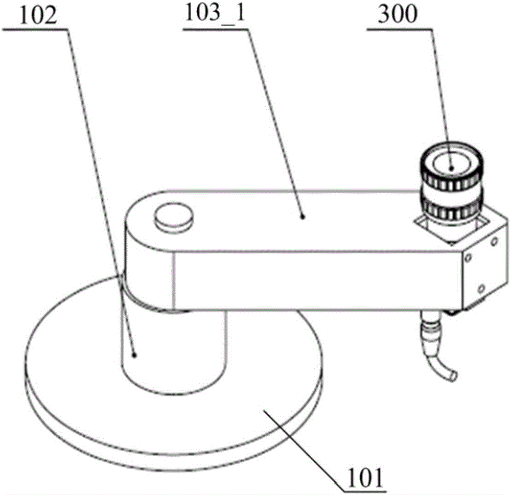
[0079] For ease of understanding, this embodiment provides a specific implementation example of the rotating multi-angle shooting bracket listed in Embodiment 1 in Mode 1. Here, the specified object is a camera in an image acquisition device as an example for illustration. see figure 1 The shown structural diagram of a multi-angle shooting bracket specifically includes a flat base 101, a rotating shaft 102 and a rotating support arm 103_1, and one end of the rotating support arm 103_1 is provided with a card position for fixing the camera. also, figure 1 The camera 300 is also shown in , and the camera 300 can be fixed on the card position of the rotating support arm 103_1.

[0080] Wherein, the flat base 101 is shown in a disc shape, and other shapes may also be used in specific applications, as long as the rotating shaft 102 can be stably fixed.

[0081] The rotating support arm 103_1 can make a circular motion with the rotation of the rotating shaft 102, thereby driving t...

Embodiment 3

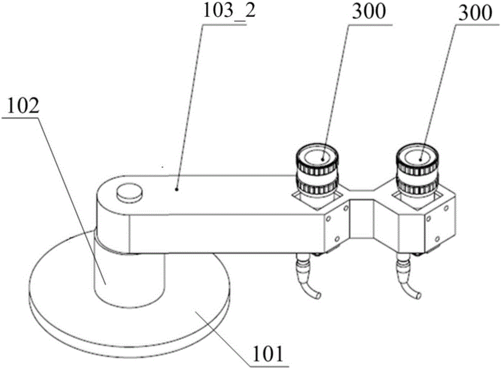
[0084] Corresponding to the second embodiment, the embodiment of the present invention provides another multi-angle shooting bracket, see image 3 A structural schematic diagram of a multi-angle shooting bracket shown, image 3 It also includes a flat base 101, a rotating shaft 102 and a rotating support arm 103_2, image 3 and figure 2 The difference is that one end of the rotating support arm 103_2 is provided with two card slots for fixing the camera, image 3 Also shown in the figure are two cameras 300 fixed on two card slots.

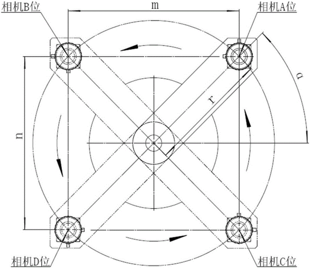
[0085] The rotating support arm 103_2 can drive the two cameras 300 to rotate along with the rotation of the rotating shaft 102. For details, see Figure 4 A schematic diagram of the shooting process of a camera is shown. The rotating support arm rotates one circle, and the camera on the outside (distance R from the rotation axis) is divided into camera points on the circumference (also called camera A positions, the same below), Camera point...


PUM


Abstract

The invention provides a multi-angle shooting support and system, and relates to the technical field of shooting. The support comprises a base, a supporting arm and a connecting portion arranged between the base and the supporting arm; the supporting arm and the base can relatively move under the effect of the connecting portion; the supporting arm is used for containing at least one designated object which is fixed to the supporting arm or can move along the supporting arm; each designated object comprises an image collection device or a shot object; each image collection device comprises a camera or a microscope. By means of the multi-angle shooting support, the positions of the image collection devices or the shot objects are transformed to achieve multi-angle shooting, the shooting effect is good, and the cost is low.

Description

technical field [0001] The invention relates to the technical field of three-dimensional shooting, in particular to a multi-angle shooting bracket and system. Background technique [0002] In technologies such as three-dimensional stereoscopic display, in order to obtain objects to be photographed from multiple angles, multiple cameras are usually installed in a fixed mechanical structure to photograph the objects. [0003] In the related art, a camera matrix formed by four digital cameras is usually used to shoot the object to be photographed. However, this method may have the following problems: [0004] (1) Since the digital camera itself has a casing, and the casing has a certain size, the lenses of the four digital cameras are all located in the middle of the digital camera, and the distance between the lenses of two adjacent digital cameras is at least one The housing width of the digital camera cannot be further reduced, so that the size of the mechanism cannot be fu...

Claims


Application Information

Patent Timeline
IPC IPC(8): F16M11/08F16M11/04G03B17/56
CPCF16M11/04F16M11/08G03B17/561
Inventor 曹亮刘忠辉
Owner BEIJING QINGYING MACHINE VISUAL TECH CO LTD
Why Eureka
Try Eureka