Electromagnetic range

An electromagnetic cooker and thermistor technology, applied in the field of electromagnetic cookers, can solve the problems of temperature difference, hysteresis, and the inability to realize precise temperature control functions, and achieve the effect of reducing temperature measurement error and reducing hysteresis effect.

Active Publication Date: 2017-01-11
SHENZHEN TOPBAND CO LTD
View PDF4 Cites 4 Cited by
  • Summary
  • Abstract
  • Description
  • Claims
  • Application Information

AI Technical Summary

Problems solved by technology

[0002] When the induction cooker is working, the utensils on the induction cooker will heat themselves. For the temperature change of the induction cooker to monitor the utensils, it is generally realized by a temperature controller installed at the bottom of the glass-ceramic plate, and the heat is transmitted through the micro-crystalline plate. The thermostat will produce hysteresis and there is a temperature difference, it is difficult to monitor the temperature of the vessel in real time
[0003] At present, the temperature measurement methods of electromagnetic cookers usually include: 1. Install an NTC (thermistor) on the bottom of the glass panel, that is, inside the machine. The NTC touches the bottom of the glass panel to measure the temperature of the inner surface of the glass panel; The temperature element is located on the bottom of the glass panel, which is also inside the machine. By receiving the infrared light passing through the glass panel, it can identify the temperature of the object that emits or refracts the infrared light. These temperature measurement schemes have more or less the difference between the measured value and the actual value. Due to the temperature difference and hysteresis effect, the temperature measurement technology of induction cooker products cannot keep up with the functional development requirements of induction cooker products, and most of the functions that require precise temperature control cannot be realized.

Method used


Image

  • Electromagnetic range
  • Electromagnetic range

Examples


Embodiment Construction

[0019] In order to have a clearer understanding of the technical features, purposes and effects of the present invention, the specific implementation manners of the present invention will now be described in detail with reference to the accompanying drawings.

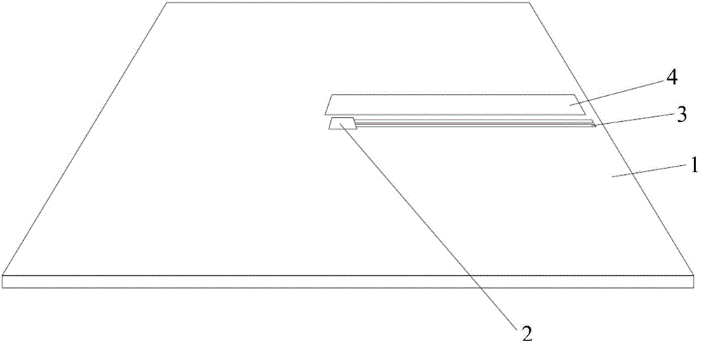
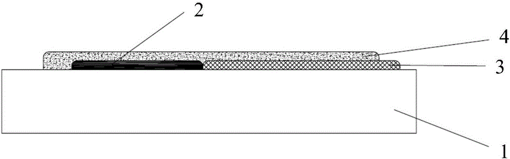
[0020] The invention discloses an electromagnetic cooker, such as Figure 1-Figure 2 As shown, the electromagnetic range includes a glass panel 1, at least one thermistor 2 and a conductive ink layer 3 are arranged on the surface of the heating area of ​​the glass panel 1; one end of the conductive ink layer 3 is connected to the thermistor 2, and the other end is connected to the thermistor 2. The control circuit of electromagnetic range is connected; The thermistor 2 and the conductive ink layer 3 are provided with an insulating ink layer 4, and the insulating ink layer 4 covers the thermistor 2 and the conductive ink layer 3, so that the thermistor 2 and the conductive ink layer 3 Not exposed. The invention can real...


PUM


Abstract

The invention relates to an electromagnetic range. The electromagnetic range comprises a glass panel; at least one thermistor and at least one conductive ink layer are arranged on the surface of a heating area of the glass panel; one end of each conductive ink layer is connected with the thermistor, and the other end is connected with a control circuit of the electromagnetic range; and an insulation ink layer is arranged on the at least one thermistor and the at least one conductive ink layer and covers the at least one thermistor and the at least one conductive ink layer, so that the at least one thermistor and the at least one conductive ink layer are not exposed. With the electromagnetic range, the temperature is measured directly, the temperature measuring error and the retardation effect are reduced, and the duration and degree of heating is controlled by a user conveniently and timely.

Description

technical field [0001] The present invention relates to the technical field of electromagnetic cooktops, and more specifically, to an electromagnetic cooktop. Background technique [0002] When the induction cooker is working, the utensils on the induction cooker will heat themselves. For the temperature change of the induction cooker to monitor the utensils, it is generally realized by a temperature controller installed at the bottom of the glass-ceramic plate, and the heat is transmitted through the micro-crystalline plate. The thermostat will produce hysteresis and there is a temperature difference, so it is difficult to monitor the temperature of the vessel in real time. [0003] At present, the temperature measurement methods of electromagnetic cookers usually include: 1. Install an NTC (thermistor) on the bottom of the glass panel, that is, inside the machine. The NTC touches the bottom of the glass panel to measure the temperature of the inner surface of the glass pan...

Claims


Application Information

Patent Timeline
Patent Type & Authority Applications(China)
IPC IPC(8): F24C7/08
CPCF24C7/08F24C7/083
Inventor 梁仕林梁峰
Owner SHENZHEN TOPBAND CO LTD
Why Eureka
Try Eureka