A plate and tube heat exchanger type shampoo bed

A technology of heat exchanger and shampoo bed, which is applied in the field of shampoo bed, can solve the problems of hair, hair cream, dirt clogging and deposition, waste heat recovery, waste heat recovery reduction, waste heat recovery efficiency reduction, etc., to achieve smooth flow of sewage, Increased heat exchange area and low maintenance costs

Active Publication Date: 2018-06-19
东莞市康源节能科技有限公司
View PDF7 Cites 0 Cited by
  • Summary
  • Abstract
  • Description
  • Claims
  • Application Information

AI Technical Summary

Problems solved by technology

[0002] Chinese patent ZL201320640979X discloses a waste heat recovery heat pump device and shampoo bed. The waste heat recovery part is inevitably connected to the evaporation end of the heat pump, and the waste heat recovery adopts an immersion structure. When used for a long time, it will cause sewage in the waste heat recovery part. When the temperature drops, when the waste water is mixed with the waste ice water in the next use, the amount of waste heat recovery will be reduced, and the efficiency of waste heat recovery will be reduced.
The serpentine heat exchange tube needs support, and the support of the serpentine heat exchange tube and the serpentine heat exchange tube itself become obstacles in the sewage flow channel of the heat exchanger, which is particularly easy to cause hair, hair cream, and dirt blockage and deposition, and the cleaning frequency is high. Cleaning is also more troublesome, and the defects are very obvious

Method used


Image

  • A plate and tube heat exchanger type shampoo bed
  • A plate and tube heat exchanger type shampoo bed
  • A plate and tube heat exchanger type shampoo bed

Examples


Embodiment 1

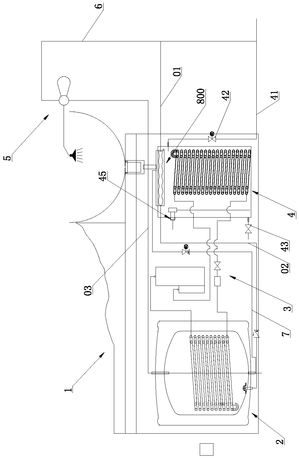
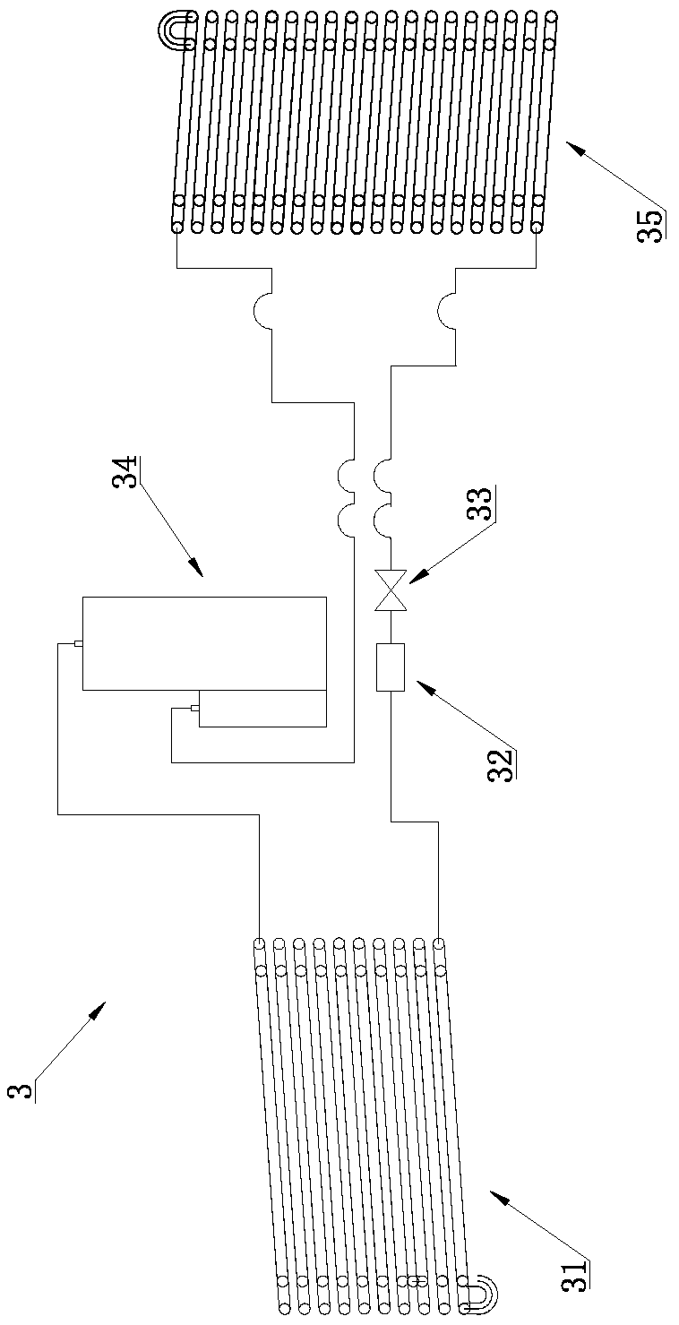
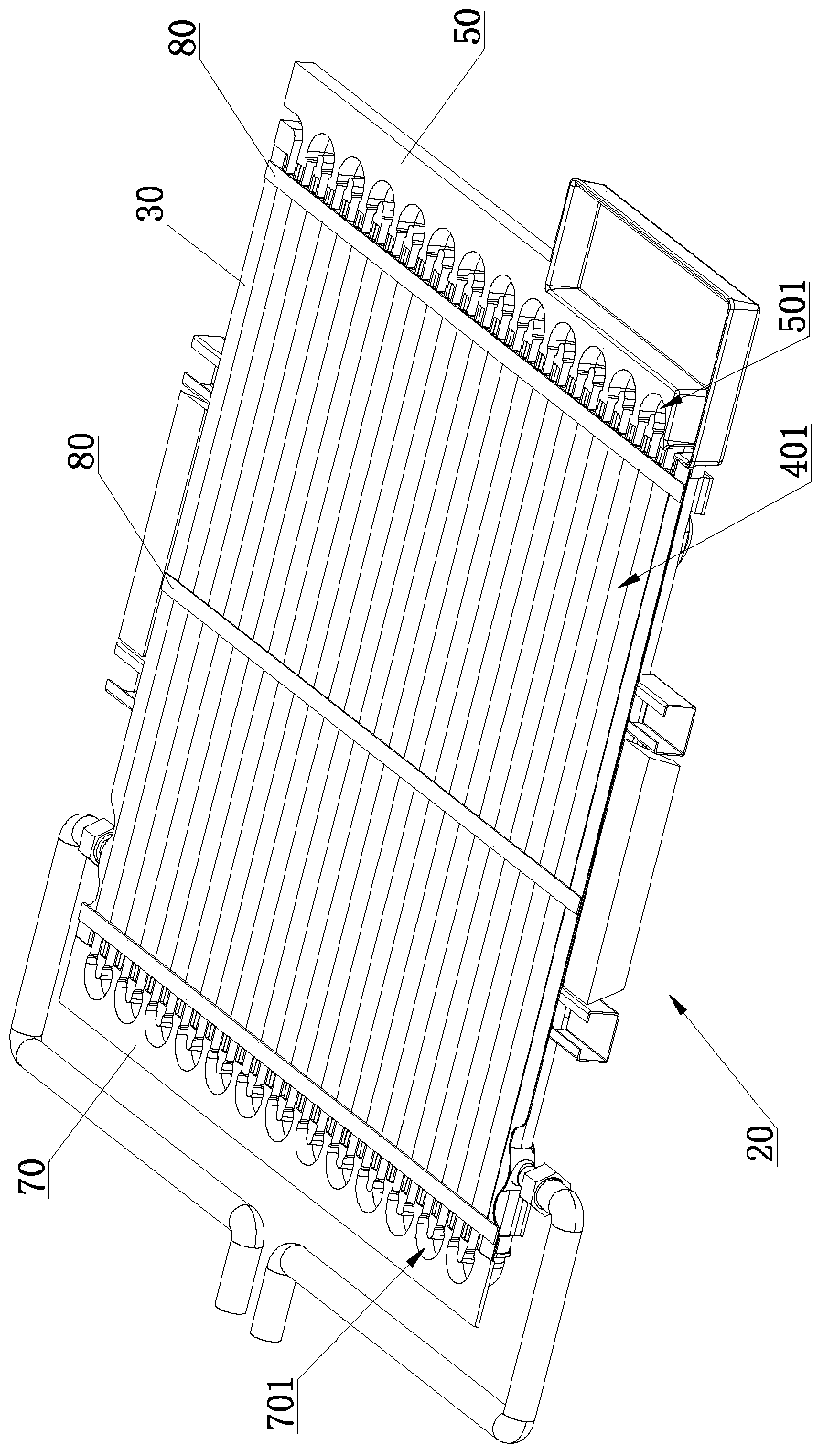
[0048] Such as Figure 1 to Figure 10 As shown, a plate and tube heat exchanger type shampoo bed includes a shampoo bed body 1, a hot water tank 2, a heating device 3 for heating the water in the hot water tank 2, and a heating device 3 communicating with the hot water tank 2. The water mixing valve assembly 5 and the cold water inlet pipe 6 communicated with the mixing valve assembly 5 also include a plate and tube heat exchanger 800 and a heat exchange inlet pipe 01; the plate and tube heat exchanger 800 includes a core body 20, a core body 20 Including A plate 30, B plate 40, front sealing plate 50 and rear sealing plate 70; A plate 30 is provided with several A plate sinking grooves 301 side by side, and the back of A plate sinking groove 301 is A plate sinking groove protrusion 302; 40 is provided with a B-plate sinker 401 corresponding to the A-plate sinker 301, and the back of the B-plate sinker 401 is a B-plate sinker protrusion 402, and two adjacent B-plate sinkers 40...

Embodiment 2

[0083] Such as Figure 11 to Figure 13 As shown, the difference between the second embodiment and the first embodiment is that the plate and tube heat exchanger 800 also includes a cover plate 10 covering the A plate 30, the cover plate 10 is provided with a water leakage hole 101, and the water leakage hole 101 A filter screen 102 is provided at the place, and the front sealing plate 50 is provided with a sump 503 for collecting the fluid flowing out of the leakage hole 101. The sump 503 communicates with the A plate sink 301, and the leakage hole 101 is connected with the shampoo bed body. The sewage outlet of 1 is connected.

[0084] In this embodiment, a cover plate 10 is added, and the cover plate 10 covers the plate A 30 so as to seal the sinker groove 301 of the plate A. In actual application, the cover plate 10 may or may not be in contact with the protrusion on the top surface of the A plate 30 . The sewage of the shampoo bed body 1 flows in from the leak hole 101, ...

Embodiment 3

[0087] Such as Figure 14 to Figure 16 As shown, the difference between the third embodiment and the second embodiment is that the plate and tube heat exchanger 800 further includes a box body 100 , and the core body 20 is installed in the box body 100 . In actual application, when the core body 20 is installed in the box body 100, the bottom surface of the box body 100 can abut against the protrusion 402 of the sinking groove of the plate B, so that the fluid in the fluid area surrounded by the box body 100 and the sinking groove protrusion 402 of the plate B flow in tank 200, as Figure 13 shown. The bottom surface of the box body 100 may not abut against the B-board sinker protrusion 402 , so that the fluid flows between the B-board 40 and the box body 100 . On the basis of the above-mentioned embodiment 2, the tank 100 is added to introduce the sewage into the fluid tank 200, so that the tap water in the medium flow channel 60 absorbs the heat of the sewage in the fluid ...


PUM


Abstract

The invention relates to the technical field of shampoo beds, in particular to a tube-on-sheet heat exchanger type shampoo bed. The tube-on-sheet heat exchanger type shampoo bed comprises a shampoo bed body, a hot water tank, a heating device for heating water in the hot water tank, a water mixing valve assembly communicated with the hot water tank and a cold water inlet pipe communicated with the water mixing valve assembly and further comprises a tube-on-sheet heat exchanger and a heat exchange water inlet pipe. The tube-on-sheet heat exchanger type shampoo bed can recover hygienic hot water waste heat immediately and low-grade fluid heat, saves energy and is environmentally friendly, the energy consumption caused by tap water heating is reduced, resources are saved, and the usage cost is reduced. The plate A and the plate B are combined to form the core body by adopting sheet pipe structures, the overall smoothness of a plate A sinking tank is good, sewage is smooth to flow, and the problem of remarkable reduction of the heat transfer coefficient due to dirt blockage and sedimentation is avoided. In addition, tap water is good in heat absorption effect in a medium channel, and the waste water and tap water heat exchange effect is good.

Description

technical field [0001] The invention relates to the technical field of hair washing bed, in particular to a plate and tube heat exchanger type hair washing bed. Background technique [0002] Chinese patent ZL201320640979X discloses a waste heat recovery heat pump device and shampoo bed. The waste heat recovery part is inevitably connected to the evaporation end of the heat pump, and the waste heat recovery adopts an immersion structure. When used for a long time, it will lead to sewage in the waste heat recovery part. When the temperature is lowered, when the waste water is mixed with the waste ice water in the next use, the amount of waste heat recovered will be reduced, and the efficiency of waste heat recovery will be reduced. [0003] At present, there are also some shampoo beds that use other waste heat recovery devices to recover the waste temperature of the sewage, but due to the limitation of the structure of the waste heat recovery devices, the problem of blockage o...

Claims


Application Information

Patent Timeline
Patent Type & Authority Patents(China)
IPC IPC(8): F28D1/03F28F3/12A45D19/00
CPCA45D19/00F28D1/0316F28F3/12
Inventor 张加振
Owner 东莞市康源节能科技有限公司
Why Eureka
Try Eureka