Power cable fault monitoring platform

A fault monitoring and power cable technology, applied in fault location, fault detection according to conductor type, signal transmission system, etc., can solve the problems of many robots and high cost, and achieve the effect of reducing cost, low cost and construction difficulty

Active Publication Date: 2017-01-11
PINGDINGSHAN POWER SUPPLY ELECTRIC POWER OF HENAN
View PDF6 Cites 10 Cited by
  • Summary
  • Abstract
  • Description
  • Claims
  • Application Information

AI Technical Summary

Problems solved by technology

But this invention has more devices above the ground, more robots, and high cost

Method used


Image

  • Power cable fault monitoring platform
  • Power cable fault monitoring platform
  • Power cable fault monitoring platform

Examples


Embodiment 1

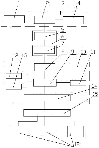
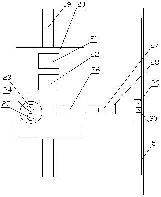
[0027] Such as figure 1 and figure 2 As shown: this embodiment provides a power cable fault monitoring platform, including a fault detector 18 arranged on the cable line, a signal return mechanism 6 arranged in the cable trench, a monitoring center 3 and a mobile monitoring device connected to it unit, the mobile monitoring unit includes an overhead track 19 set in the cable trench, a moving mechanism 20 set on the overhead track 19, a monitoring terminal 10 set on the moving mechanism 20, and the signal return mechanism 6 Comprising a communication line 5 set in a cable trench and several data interface modules 7 set on the communication line 5, the fault detector 18 is provided with a first wireless communication module 15, and the monitoring terminal 10 includes a control module 9, a second Wireless communication module 14, storage module 11, sensor module 12, video surveillance module 13 and the data transmission module 8 that corresponding described data interface modul...

Embodiment 2

[0030] Such as figure 1 and figure 2 Shown: its difference with embodiment one is:

[0031] The moving mechanism 20 is provided with an ultrasonic generator 21 and an extermination device 22, and the extermination device 22 adopts an electric shock type insect extermination lamp. The ultrasonic generator can expel snakes and rats to prevent them from affecting the mobile monitoring unit. The insect extermination device adopts an electric shock type insect extermination lamp, which has high insect extermination efficiency, and the mosquito corpse is very light after the electric shock.

[0032] The monitoring center 3 includes an industrial computer 2 , a database server 1 and a GIS module 4 . The monitoring center uses the industrial computer to receive the fault information and image information sent by the mobile monitoring unit. The database server can store the monitored information. The location of the fault point and its surrounding environment are clearly displayed ...

Embodiment 3

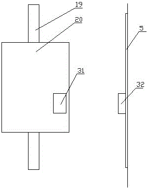
[0036] Such as image 3 Shown: its difference with embodiment two is:

[0037] The data interface module 7 includes a wireless receiver 32, and the mobile mechanism 20 is provided with a wireless transmitter 31 connected to the control module 9. In this embodiment, the data interface module adopts a wireless communication method, which can simplify the movement. The equipment on the mechanism no longer needs devices such as plugs and telescopic rods, but only transmits information wirelessly when the mobile monitoring unit moves to the side of the data interface module. The wireless receiver and wireless transmitter can use RS485 to WIFI, and the data transmission is more convenient.


PUM


Abstract

The invention discloses a power cable fault monitoring platform. The power cable fault monitoring platform comprises a fault detector arranged on a cable line, a signal return mechanism arranged in a cable duct, a monitoring center and a movable monitoring unit connected with the monitoring center, wherein the movable monitoring unit comprises an overhead track formed in the cable duct, a moving mechanism arranged on the overhead track and a monitoring terminal arranged on the moving mechanism, the signal return mechanism comprises a communication line arranged in the cable duct and a plurality of data interface modules formed in the communication line, and the fault detector is provided with a first wireless communication module. The fault detection of the whole cable and monitoring environment information and device information in the cable duct can be achieved only by using a small number of sensors, an online current mode is acquired in real time through the fault detector to conduct comprehensive monitoring on line faults, and fault judgment is more timely and accurate.

Description

technical field [0001] The invention relates to the technical field of transmission line cable fault monitoring, in particular to a power cable fault monitoring platform. Background technique [0002] Power cables are cables used to transmit and distribute electric energy. Power cables are often used in urban underground power grids, outgoing lines of power stations, internal power supply of industrial and mining enterprises, and underwater transmission lines across rivers and seas. In power lines, the proportion of cables is gradually increasing. Power cables are cable products used to transmit and distribute high-power electric energy in the main line of the power system, including 1-500KV and above various voltage levels and various insulated power cables. [0003] Due to its hidden laying, convenient maintenance, reliable operation and beautifying the environment, power cable lines have been popularized in power supply lines in cities, factories, and enterprises. Howev...

Claims


Application Information

Patent Timeline
Patent Type & Authority Applications(China)
IPC IPC(8): G01R31/08G08C17/02
CPCG01R31/085G08C17/02
Inventor 刘震王正钊曹建军智勇军李庆盈郑俊洋陈瑾董晓晨高明姬恒飞王振方
Owner PINGDINGSHAN POWER SUPPLY ELECTRIC POWER OF HENAN
Why Eureka
Try Eureka