Power cable fault positioning platform

A fault location, power cable technology, applied in fault location, fault detection according to conductor type, TV and other directions, can solve the problems of many robots and high cost, and achieve the effect of cost reduction, low cost and construction difficulty.

Active Publication Date: 2017-08-11
PINGDINGSHAN POWER SUPPLY ELECTRIC POWER OF HENAN
View PDF8 Cites 12 Cited by
  • Summary
  • Abstract
  • Description
  • Claims
  • Application Information

AI Technical Summary

Problems solved by technology

But this invention has more devices above the ground, more robots, and high cost

Method used


Image

  • Power cable fault positioning platform
  • Power cable fault positioning platform
  • Power cable fault positioning platform

Examples


Embodiment 1

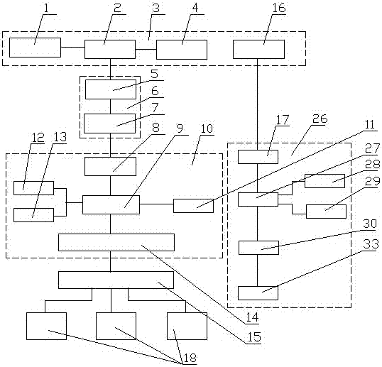
[0027] Such as figure 1 , figure 2 and Figure 4 As shown: this embodiment provides a power cable fault location platform, including a fault detector 18 arranged on the cable line, a signal return mechanism 6 arranged in the cable trench, a mobile monitoring station 3 and a mobile monitoring unit. The mobile monitoring unit includes an overhead track 19 set in the cable trench, a moving mechanism 20 set on the overhead track 19, a monitoring terminal 10 set on the moving mechanism 19, and the signal return mechanism 6 includes a cable trench The set communication line 5 and several wireless receivers 7 set on the communication line 5, the fault detector 18 sets the first wireless communication module 15, and the monitoring terminal 10 includes a control module 9, a second wireless communication module 14, storage module 11, sensor module 12, video monitoring module 13 and the wireless transmitter 8 that corresponding described wireless receiver 7 is arranged, described mobi...

Embodiment 2

[0030] like figure 1 and figure 2 Shown: its difference with embodiment one is:

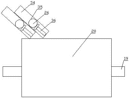
[0031] Described fault location mechanism 26 comprises spherical transparent casing 35, and power supply 33, warning light 28, zigbee module 17, vibration sensor 29 and controller 27 are set in described transparent casing 35, and described controller 27 is connected with power supply respectively. 33. The alarm lamp 28, the zigbee module 17 and the vibration sensor 29 are connected; the transparent housing 35 is made of elastic plastic; a main switch 30 is set between the power supply 33 and the controller 27, and the main switch 30 is set In the transparent casing 35; the ejection mechanism includes several ejection cylinders 34 arranged obliquely on the moving mechanism 20, the bottom of the ejection cylinder 34 is provided with a telescopic ejector rod 36, and the telescopic ejector rod 36 is provided with the Fault location mechanism 26, described telescopic push rod 36 is connected with ...

Embodiment 3

[0035] like figure 1 and image 3 Shown: its difference with embodiment two is:

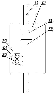
[0036] The moving mechanism 20 is provided with an ultrasonic generator 21 and an extermination device 22, and the extermination device 22 adopts an electric shock type insect extermination lamp. The ultrasonic generator can expel snakes and rats to prevent them from affecting the mobile monitoring unit. The insect extermination device adopts an electric shock type insect extermination lamp, which has high insect extermination efficiency, and the mosquito corpse is very light after the electric shock.

[0037] The sensor module 12 includes a temperature sensor, a humidity sensor, an open flame sensor, a combustible gas sensor and a water level sensor. The temperature sensor monitors the temperature around the cable, the humidity sensor monitors the ambient humidity around the cable, the open flame sensor uses the ultraviolet rays in the open flame to monitor whether there is burning around the ...


PUM


Abstract

The invention discloses a power cable fault positioning platform, including a cable fault detector arranged on a power cable, a signal back-transmission mechanism, a mobile monitoring station and a mobile monitoring unit. The mobile monitoring unit comprises an overhead track and a mobile mechanism wherein the mobile mechanism is provided with a monitoring terminal; the signal back-transmission mechanism comprises a communication line arranged in a cable conduit and a number of wireless receivers; the fault detector is provided with a first wireless communication module; the monitoring terminal comprises a control module, a second wireless communication module, a storage module, a sensor module, a video monitoring module and wireless emitters arranged correspondingly to the wireless receivers; and the mobile mechanism is provided with a plurality of fault positioning mechanisms through an ejection mechanism. The platform of the invention performs comprehensive monitoring to the cable fault through the real-time acquisition of online current by the fault detector and through the fault point positioning, allows the workmen to quickly find the specific fault position so as to realize the rapid maintenance to the fault point.

Description

technical field [0001] The invention relates to the technical field of transmission line cable fault monitoring, in particular to a power cable fault location platform. Background technique [0002] Power cables are cables used to transmit and distribute electric energy. Power cables are often used in urban underground power grids, outgoing lines of power stations, internal power supply of industrial and mining enterprises, and underwater transmission lines across rivers and seas. In power lines, the proportion of cables is gradually increasing. Power cables are cable products used to transmit and distribute high-power electric energy in the main line of the power system, including 1-500KV and above various voltage levels and various insulated power cables. [0003] Due to its hidden laying, convenient maintenance, reliable operation and beautifying the environment, power cable lines have been popularized in power supply lines in cities, factories, and enterprises. However...

Claims


Application Information

Patent Timeline
Patent Type & Authority Applications(China)
IPC IPC(8): G01R31/08G01D21/02H04N7/18G08C17/02
CPCG01D21/02G01R31/083G01R31/085G08C17/02H04N7/18H04N7/183
Inventor 周志锋梁峰云智勇军陆畅郑俊洋吕杰迟成王振方李晓航
Owner PINGDINGSHAN POWER SUPPLY ELECTRIC POWER OF HENAN
Why Eureka
Try Eureka