Multi-function automatic tool for electric insurance maintenance

An automatic tool and multi-functional technology, applied in the direction of overhead line/cable equipment, etc., can solve the problems of reducing work efficiency, increasing safety hazards, cumbersome replacement operations, etc., to improve work efficiency, improve safety and work efficiency, and multi-function Effect

Active Publication Date: 2018-04-24
LIANSHAN POWER SUPPLY COMPANY OF STATE GRID SICHUAN ELECTRIC POWER +1
View PDF6 Cites 0 Cited by
  • Summary
  • Abstract
  • Description
  • Claims
  • Application Information

AI Technical Summary

Problems solved by technology

[0003] The purpose of the present invention is to solve the problems in the prior art that there are many types of tools for electric insurance inspection and maintenance, and the replacement operation is very cumbersome, resulting in reduced work efficiency and increased safety hazards. The present invention provides a multifunctional electric electric insurance inspection and maintenance automatic tool

Method used


Image

  • Multi-function automatic tool for electric insurance maintenance
  • Multi-function automatic tool for electric insurance maintenance
  • Multi-function automatic tool for electric insurance maintenance

Examples


Embodiment 1

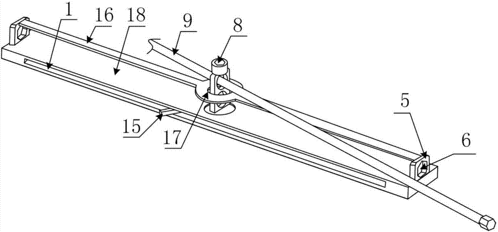
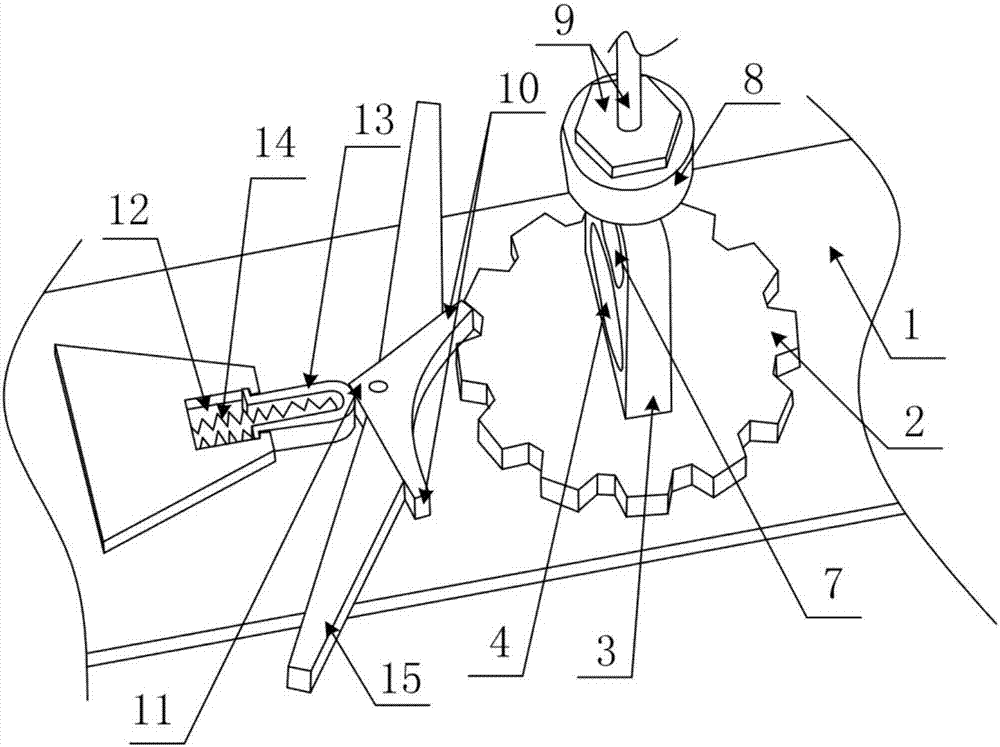
[0029] Multifunctional power insurance maintenance automatic tools, such as figure 1 with figure 2 As shown, it includes the base plate 1, the gear 2 fixed above the base plate 1 through the first rotating shaft, the rotating handle 3 arranged on the gear 2, the rope hole 4 arranged on the rotating handle 3, and the gears fixed on both sides of the gear 2 respectively. The thread passing plate 5 on the bottom plate 1 is arranged on the hexagonal bolt hole 6 on the thread passing plate 5 , and the limiting device for limiting the rotation direction of the gear 2 is arranged on the bottom plate 1 .

[0030] In order to facilitate operation, the bottom end of the rotating handle 3 is fixedly connected with the gear 2, the rotating handle 3 is also provided with an operating hole 7 above the rope hole 4, and the top of the rotating handle 3 is also provided with a screw operating rod interface 8; The screw operating rod interface 8 is provided with a screw operating rod 9 . The...

Embodiment 2

[0035] The difference between this embodiment and Embodiment 1 is that this embodiment increases the structure of the connecting rod 16 and the tool upper cover 18, and the specific settings are as follows:

[0036] Such as figure 1 As shown, the top ends of the wire passing boards 5 on both sides of the gear 2 are connected by a connecting rod 16, and the connecting rod 16 above the gear 2 is also provided with a positioning hole 17. A tool upper cover 18 for covering the limit device and the gear 2 is also arranged between the connecting rod 16 and the bottom plate 1 .

Embodiment 3

[0038] The difference between this embodiment and Embodiment 1 is that this embodiment increases the function of the cutter, and the specific settings are as follows:

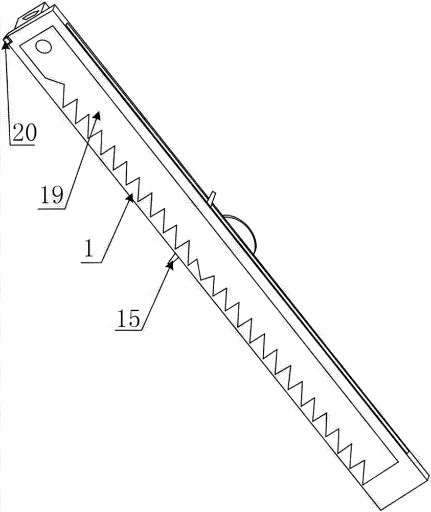
[0039] The bottom of the base plate 1 is also hinged with a cutter 19 through the third rotating shaft, and the bottom of the base plate 1 is also provided with a stop nail 20 that limits the position of the cutter 19, such as image 3 with Figure 4 shown.


PUM


Abstract

The invention discloses a multifunctional power insurance overhaul automatic tool. The tool solves the problems that in the prior art, during power insurance overhaul, the number of tool types is large, replacement operation is very complex, accordingly work efficiency is reduced, and safety hidden hazards are increased. The tool comprises a bottom plate (1), a gear (2) fixed to the upper side of the bottom plate (1) through a first rotary shaft, a rotary handle (3) arranged on the gear (2), a rope penetrating hole (4) formed in the rotary handle (3), wire passing plates (5) fixed to the portions, on the two sides of the gear (2), on the bottom plate (1) respectively, hexagonal bolt holes (6) formed in the wire passing plates (5), and a limiting device arranged on the bottom plate (1) and used for limiting the rotation direction of the gear (2). The tool has the advantages of being small in size, multifunctional and very convenient to use for work in a high-altitude narrow space, improving construction safety and work efficiency and the like.

Description

technical field [0001] The invention relates to a maintenance tool, in particular to a multifunctional electric insurance maintenance automatic tool. Background technique [0002] At present, there are no special tools for electric power insurance maintenance work. During insurance maintenance, workers will carry various operating tools such as overhead racks when working. Also efficiency is low work efficiency greatly; And owing to be high-altitude operation, when tool is too much, also increased the worker's construction danger greatly. Contents of the invention [0003] The purpose of the present invention is to solve the problems in the prior art that there are many types of tools for electric insurance inspection and maintenance, and the replacement operation is very cumbersome, resulting in reduced work efficiency and increased safety hazards. The present invention provides a multifunctional electric electric insurance inspection and maintenance automatic tool. [...

Claims


Application Information

Patent Timeline
Patent Type & Authority Patents(China)
IPC IPC(8): H02G1/02
CPCH02G1/02
Inventor 杨登翔孙伟
Owner LIANSHAN POWER SUPPLY COMPANY OF STATE GRID SICHUAN ELECTRIC POWER
Why Eureka
Try Eureka