Automobile micromotor shell and manufacturing method thereof

A technology for micro-motor casings and automobiles, which is applied in the manufacture of motor generators, casings/covers/supports, electrical components, etc., and can solve the difficult to meet the coaxiality requirements of the casing positioning center axis and the magnet limit butterfly wings It is difficult to guarantee the dimensional accuracy, and the dimensional accuracy cannot meet the design requirements, etc., to achieve the effect of ensuring verticality, increasing the effective axial length, and preventing falling off.

Active Publication Date: 2017-01-11
常州津兆机电科技有限公司
View PDF13 Cites 8 Cited by
  • Summary
  • Abstract
  • Description
  • Claims
  • Application Information

AI Technical Summary

Problems solved by technology

[0002] At present, more and more micro-motors are used in existing passenger cars, such as: the adjustment of the front and rear positions of the car seat, the angle adjustment of the backrest and the seat, the drive of the water spray pump when cleaning the car glass, and the rearview mirror of the car. The direction adjustment, the direction adjustment of the headlights of the car, etc., the performance and safety requirements of the car are getting higher and higher, and when the existing micro-motor is manufactured, most of its shell is machined and formed or a combination of several parts Molding is realized, its manufacturing cost is high, processing efficiency is low, and the combined molding casing, due to the technical characteristics of machining, has to be re-installed and clamped during the processing of the magnet positioning protrusion on the shoulder, so that the shoulder The dimensional accuracy of the magnet positioning protrusion cannot meet the design requirements, and the processing of the middle magnet limit butterfly wing must be processed with another positioning reference, and it also needs to be reinstalled and stuck, resulting in the size of the middle magnet limit butterfly wing The accuracy is also difficult to guarantee, especially the bearing chamber at the end of the casing, it is even more difficult to meet the coaxiality requirement with the positioning center axis of the entire casing. Since the fixed part used for bearing fixing has the requirement of being vertical to the axis of rotation of the bearing, machining must It can only be guaranteed by the tool retraction process at the bottom of the bearing chamber, which greatly reduces the axial fit length of the bearing chamber. Therefore, due to the characteristics of machining, it is difficult to ensure the axial fit length of the bearing and ensure that the fixed part and the The verticality of the center of rotation of the bearing chamber; some of them are formed by sheet stretching, but they are all realized by a single process and a single die. Compared with the machined casing, although there is some progress, it still needs to be positioned differently , or the problem of secondary positioning is also difficult to achieve, that is, to ensure the axial matching length of the bearing, and to ensure the perpendicularity between the fixed part and the center of rotation of the bearing chamber, and it is also difficult to locate the bearing chamber at the end of the casing and the entire casing The coaxiality of the central shaft is required, but with the bumps of the road, the vibration of the body and the long-term rotation of the car during driving, if there is no axial matching length of the bearing and the axial positioning part of the end of the bearing and the rotation of the bearing chamber If the verticality of the center is guaranteed, the bearing will loosen with the casing, causing noise, and some bearings will even loosen and fall off, which seriously affects the normal operation of the motor and poses a serious safety hazard. It is urgent to break through the existing products. Defects, develop and manufacture safe and reliable automotive micro-motor housings

Method used


Image

  • Automobile micromotor shell and manufacturing method thereof
  • Automobile micromotor shell and manufacturing method thereof
  • Automobile micromotor shell and manufacturing method thereof

Examples


Embodiment Construction

[0028] In order to make the content of the present invention more clearly understood, the present invention will be further described in detail below based on specific embodiments and in conjunction with the accompanying drawings.

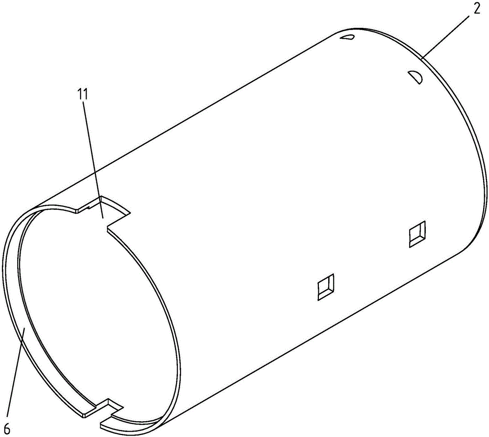
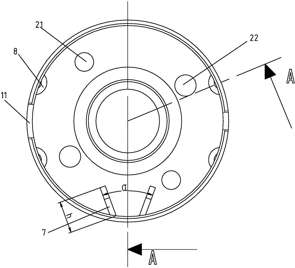
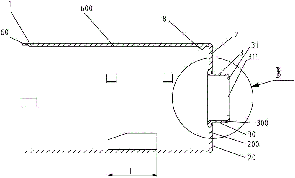
[0029] like Figure 1~4 Shown, a kind of automobile micro-motor casing, this casing is made into a generally hollow cylindrical casing with a bottom by punching, punching, stretching, and stamping forming of a thin steel plate for many times. One end of the housing is an open end 1, and the other end of the housing is formed with a cylinder bottom 2, and the cylinder bottom 2 is provided with a bearing chamber 3 protruding axially outward and accommodating bearings. The bearing chamber 3 The axially outer end of the cylinder is provided with a fixing portion 31 for fixing the axial end of the bearing. The fixing portion 31 is provided with a through hole 311 for the motor shaft to protrude. The transition area between the radially outer wall surfa...


PUM


Abstract

The invention discloses an automobile micromotor shell and a manufacturing method thereof. The automobile micromotor shell comprises a cylindrical shell body, one end of the shell body serves as the opening end, a cylinder bottom is formed at the other end of the shell body, a bearing chamber which axially protrudes outwards and contains a bearing is arranged at the cylinder bottom, the axial outer end of the bearing chamber is provided with a fixing part used for fixing the axial end of the bearing, and a through hole used for allowing a motor shaft to stretch out is formed in the fixing part; a dented groove which is axially dented inwards is formed in a transition region between the axial outer wall surface of the cylinder bottom and the radial outer wall surface of the bearing chamber, and a convex rib which corresponds to the dented groove, protrudes towards the interior of the shell body and is used for increasing the axial effective length of the bearing chamber is formed in a transition region between the axial inner wall surface of the cylinder bottom and the radial inner wall surface of the bearing chamber. According to the automobile micromotor shell and the manufacturing method thereof, not only is the axial fitting length of an assembled bearing guaranteed, but also the perpendicularity requirement of the fixing part and the rotation center of the bearing chamber is guaranteed, and the phenomenon that normal running of a motor is affected due to the fact that noise is generated by looseness between the bearing and the fixing part is avoided.

Description

technical field [0001] The invention relates to an automobile micro-motor casing and a manufacturing method thereof, which are mainly used in small rotating machines (for example: automobile wiper water spray pumps, automobile seat moving actuators, electric ladder knives, etc.). Background technique [0002] At present, more and more micro-motors are used in existing passenger cars, such as: the adjustment of the front and rear positions of the car seat, the angle adjustment of the backrest and the seat, the drive of the water spray pump when cleaning the car glass, and the rearview mirror of the car. The direction adjustment, the direction adjustment of the headlights of the car, etc., the performance and safety requirements of the car are getting higher and higher, and when the existing micro-motor is manufactured, most of its shell is machined and formed or a combination of several parts Molding is realized, its manufacturing cost is high, processing efficiency is low, a...

Claims


Application Information

Patent Timeline
Patent Type & Authority Applications(China)
IPC IPC(8): H02K5/16H02K5/24H02K15/14
CPCH02K5/163H02K5/24H02K15/14
Inventor 王金锁阎武权
Owner 常州津兆机电科技有限公司
Why Eureka
Try Eureka