Novel drum brake wheel cylinder structure

A technology for drum brakes and wheel cylinders, which is applied in the direction of brake actuators, gear transmission mechanisms, mechanical equipment, etc., and can solve the problem of the small matching length between the outer cylindrical surface of the piston and the cylindrical surface of the inner hole of the wheel cylinder, and the problem that the piston and the inner hole of the wheel cylinder Wear and tear, cup sealing deterioration and other problems, to achieve the effect of reducing the risk of sticking, good dynamic sealing performance, and prolonging the service life

Inactive Publication Date: 2018-12-18
JILIN DONGGUANG AOWEI AUTOMOBILE BRAKE SYST
View PDF8 Cites 1 Cited by
  • Summary
  • Abstract
  • Description
  • Claims
  • Application Information

AI Technical Summary

Problems solved by technology

[0006] The invention provides a novel drum brake wheel cylinder structure to solve the problem that the piston protrudes too much relative to the wheel cylinder mouth in the existing wheel cylinder structure, the matching length between the outer cylindrical surface of the piston and the cylindrical surface of the inner hole of the wheel cylinder is very small, and the piston Under the action of the hydraulic pressure and the pressure of the brake shoe parts, it is easy to deflect, resulting in increased wear of the piston and the inner hole of the wheel cylinder, deterioration of the sealing of the cup, and even the problem of the piston returning stuck.

Method used


Image

  • Novel drum brake wheel cylinder structure
  • Novel drum brake wheel cylinder structure

Examples


Embodiment Construction

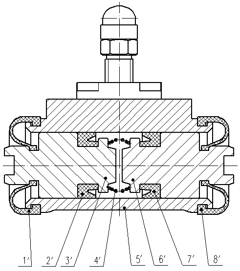
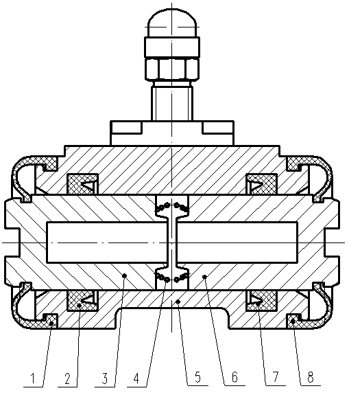
[0013] The present invention is made up of sealing function part one 1, leather cup one 2, wheel cylinder piston one 3, wheel cylinder spring 4, wheel cylinder 5, wheel cylinder piston two 6, leather cup two 7, sealing function part two 8, wheel cylinder piston One 3 and wheel cylinder piston two 6 are respectively assembled on both sides of the cylinder hole of wheel cylinder 5, the wheel cylinder 5 is in clearance fit with wheel cylinder piston one 3 and wheel cylinder piston two 6 respectively, and the sealing function part one 1 is respectively connected with the wheel cylinder piston One 3 is connected with the wheel cylinder 5, the sealing function part 2 8 is respectively connected with the wheel cylinder piston 2 6 and the wheel cylinder 5, there are two leather cup installation grooves in the inner hole of the wheel cylinder 5, the leather cup 1 2 and the leather cup 2 7 are respectively installed On the leather cup installation groove of wheel cylinder 5, wheel cylind...


PUM


Abstract

The invention relates to a novel drum brake wheel cylinder structure, and belongs to the technical field of automobile braking. A first wheel cylinder piston and a second wheel cylinder piston are assembled on the two sides of a wheel cylinder hole respectively, and a wheel cylinder is in clearance fit with the first wheel cylinder piston and the second wheel cylinder piston. A first sealing function piece is connected with the first wheel cylinder piston and the wheel cylinder separately, and a second sealing function piece is connected with the second wheel cylinder piston and the wheel cylinder separately. Two leather cup mounting grooves are formed in an inner hole of the wheel cylinder, the first leather cup and the second leather cup are arranged in the leather cup mounting grooves of the wheel cylinder respectively, and a wheel cylinder spring is installed between the first wheel cylinder piston and the second wheel cylinder piston. The first wheel cylinder piston and the secondwheel cylinder piston are provided with outer cylindrical surfaces. The novel drum brake wheel cylinder structure has the advantages that the structure is novel, the axial matching length of the wheel cylinder pistons and the wheel cylinder hole is increased, the guide performance of the wheel cylinder hole to the wheel cylinder pistons is kept, and the eccentric abrasion phenomenon of the wheelcylinder pistons in the braking process is relieved, so that the higher the roughness grade of the outer surfaces of the wheel cylinder pistons is, the better the dynamic sealing performance of the wheel cylinder pistons is.

Description

technical field [0001] The invention belongs to the technical field of automobile braking, in particular to an improvement to a drum brake wheel cylinder. Background technique [0002] Drum brakes are the brake actuators in the brake system and the key components in the car brake system. Its working principle is to use the hydraulic pressure generated by the brake master cylinder assembly to transmit to the wheel cylinder assembly in the rear drum brake through the brake pipeline. After the wheel cylinder piston pushes the brake shoe parts under the hydraulic pressure, the brake shoe Components that create frictional resistance against the drum to resist the wheel's rotation or tendency to rotate. Drum brakes have fewer components than disc brakes, have a simpler structure, and are less expensive to manufacture. [0003] When the vehicle is running normally, under the combined action of the clearance adjustment mechanism and the reset mechanism inside the drum brake, the f...

Claims


Application Information

Patent Timeline
Patent Type & Authority Applications(China)
IPC IPC(8): F16D65/14F16D121/04
CPCF16D65/14F16D2121/04
Inventor 汤颖伟杨惠子蔡云鹏徐巾巾刘欣王富辉张玉海董可心王崇
Owner JILIN DONGGUANG AOWEI AUTOMOBILE BRAKE SYST
Why Eureka
Try Eureka