
Shafts, motors and air conditioners

A technology of rotating shaft and permanent magnet motor, which is applied to electromechanical devices, electrical components, electric components, etc., can solve the problem of high difficulty of rotating shaft control, and achieve the effect of solving high control difficulty, reducing control difficulty and avoiding interference.

Active Publication Date: 2019-03-08
ZHUHAI GREE REFRIGERATION TECH CENT OF ENERGY SAVING & ENVIRONMENTAL PROTECTION
View PDF5 Cites 0 Cited by
  • Summary
  • Abstract
  • Description
  • Claims
  • Application Information

AI Technical Summary

Problems solved by technology

[0003] The main purpose of the present invention is to provide a rotating shaft, a motor and an air conditioner to solve the problem of high difficulty in controlling the rotating shaft in the prior art

Method used


Image

  • Shafts, motors and air conditioners
  • Shafts, motors and air conditioners
  • Shafts, motors and air conditioners

Examples


Embodiment Construction

[0027] It should be noted that, in the case of no conflict, the embodiments in the present application and the features in the embodiments can be combined with each other. The present invention will be described in detail below with reference to the accompanying drawings and examples.

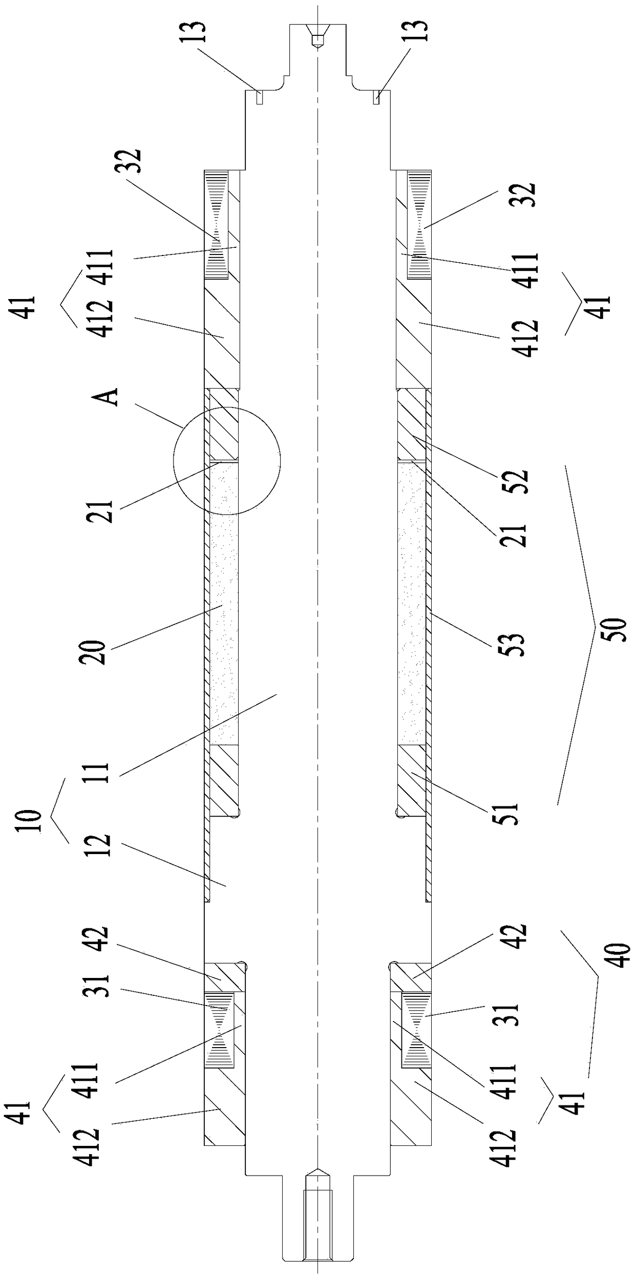
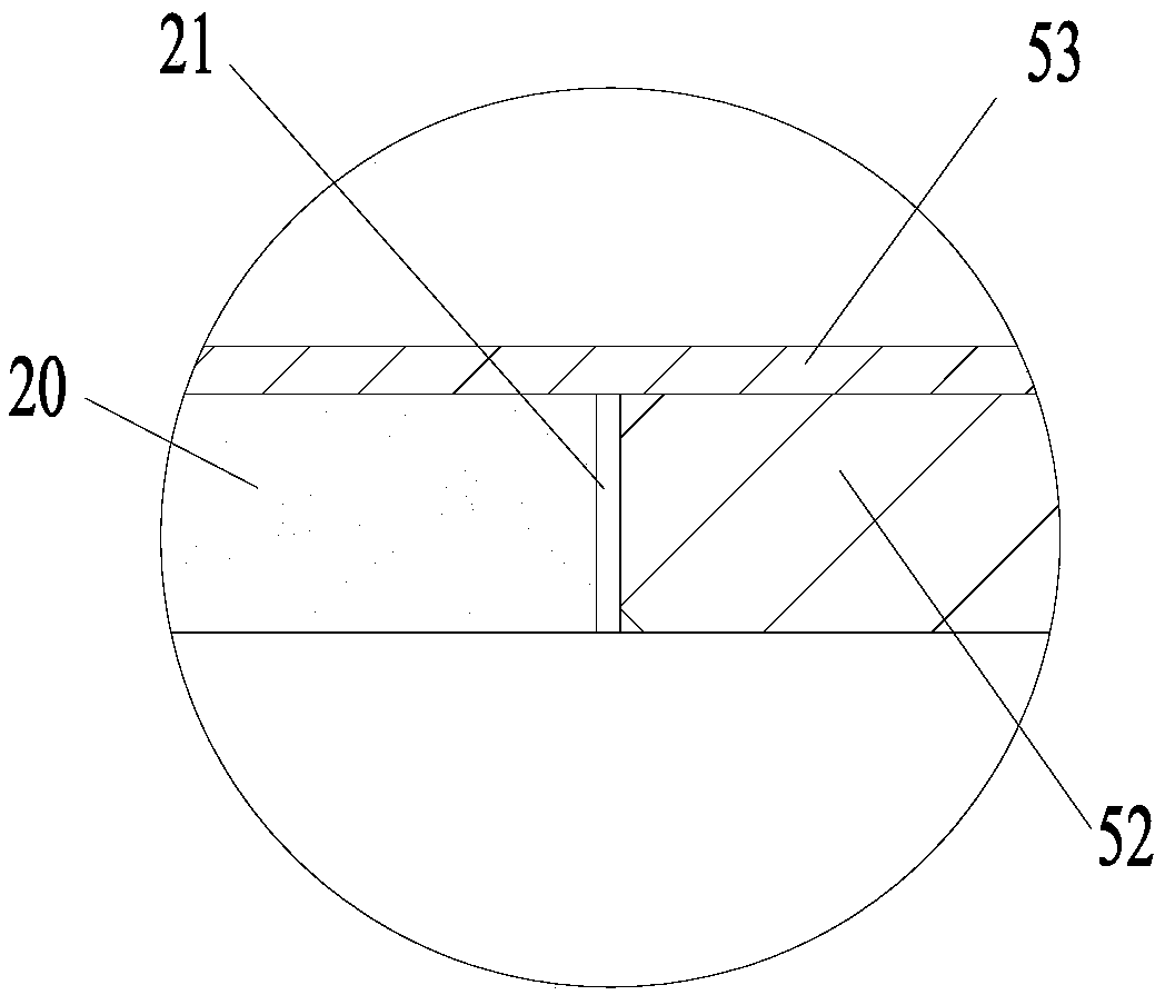
[0028] Such as figure 2 As shown, the rotating shaft of this embodiment includes a core shaft 10 , a magnetic portion 20 , a bearing rotor and a first magnetic isolation portion 40 . Wherein, the magnetic part 20 is disposed on the mandrel 10 to provide a magnetic field in a predetermined direction. The bearing rotor is sleeved on the mandrel 10 and spaced apart from the magnetic part 20 . The first magnetic isolation part 40 is sandwiched between the bearing rotor and the core shaft 10 .

[0029] Applying the technical solution of this embodiment, the rotating shaft includes a magnetic part 20 disposed on the core shaft 10 and a bearing rotor. Wherein, the magnetic portion 20 can provide ...


PUM


Abstract

A shaft, a motor, and an air conditioner are provided. The shaft comprises: a core shaft (10); a magnetic member (20) disposed on the core shaft (10) to provide a magnetic field in a predetermined direction; bearing rotors (31, 32) sleeved over the core shaft (10) and spaced apart from the magnetic member (20); and a first magnetic isolator (40) disposed between the bearing rotors (31, 32) and the core shaft (10) to magnetically isolate the bearing rotors (31, 32) and the core shaft (10). In the above structure, the bearing rotors (31, 32) are isolated from the magnetically conductive core shaft (10) by the first magnetic isolator (40), such that axial magnetic field leakage is prevented from passing through the bearing rotors (31, 32) and forming a coupling loop, thus preventing a generated coupling loop from interfering with a radial magnetic bearing magnetic field of the bearing rotors (31, 32). In this way the present invention makes it easier to control bearing rotors (31, 32) from both sides, resolving the issue in the prior art in which control of a shaft is problematic.

Description

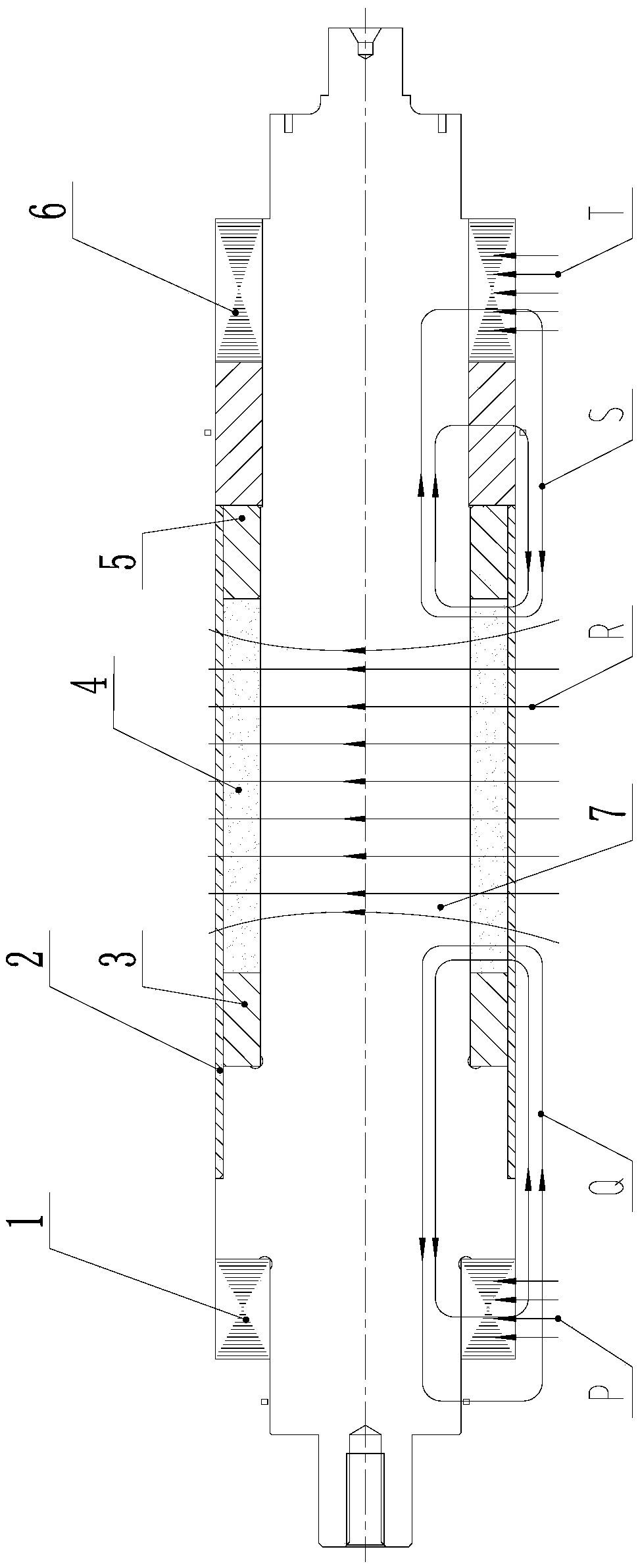
technical field [0001] The invention relates to the field of high-speed magnetic levitation, in particular to a rotating shaft, a motor and an air conditioner. Background technique [0002] The rotor structure of the high-speed permanent magnet motor in the prior art adopts a whole piece of ring-shaped magnet 4 (surface-mounted magnet), and all rotor parts are sequentially hot-packed onto the rotor mandrel 7, and the ring-shaped magnet 4 is protected by the sheath 2 and transmit torque. Ring magnetic steel 4 provides the main magnetic field of the motor, figure 1 R in is the magnetic induction line of the main magnetic field. Although the above-mentioned high-speed rotor structure uses a magnetic isolation structure (magnetic isolation baffle 3 and magnetic isolation baffle 5) for magnetic isolation treatment, its mandrel 7 is a magnetic material, and the axial leakage magnetic field of the motor rotor will pass through the mandrel 7 forms a coupling loop Q and a coupling...

Claims


Application Information

Patent Timeline
Patent Type & Authority Patents(China)
IPC IPC(8): H02K7/00H02K1/27H02K1/28H02K5/16
CPCH02K1/27H02K1/28H02K5/161H02K7/00
Inventor 李广海张小波刘健宁张芳贾金信郭长光魏琼李忠雨龚高田思园苏久展张超
Owner ZHUHAI GREE REFRIGERATION TECH CENT OF ENERGY SAVING & ENVIRONMENTAL PROTECTION
Learn More