Autorotation field-effect water treating machine

A technology of automatic rotation and field effect, applied in the direction of magnetic/electric field water/sewage treatment, etc., can solve problems such as unsatisfactory results

Inactive Publication Date: 2017-01-18
SHANDONG RINA FUNCTIOANL MATERIAL TECH CO LTD
View PDF0 Cites 2 Cited by
  • Summary
  • Abstract
  • Description
  • Claims
  • Application Information

AI Technical Summary

Problems solved by technology

Although this technical solution can change the physica

Method used


Image

  • Autorotation field-effect water treating machine
  • Autorotation field-effect water treating machine
  • Autorotation field-effect water treating machine

Examples


Embodiment 1

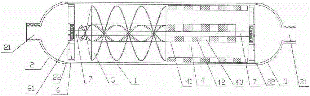
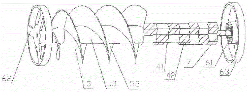
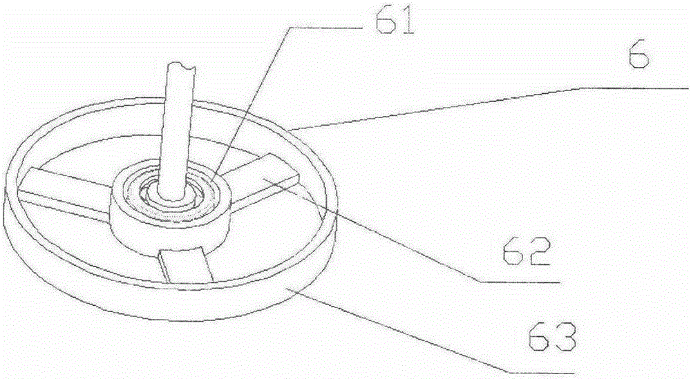
[0022] Embodiment 1: an automatic rotating field effect water treatment machine, comprising a casing 1, a water inlet 21, and a water outlet 31, characterized in that: a hydrodynamic generator 5, a magnetic hub 4, and a magnetic stator are arranged in the casing 1 8. The hydrodynamic generator 5 and the magnetic pivot 4 are solidly integrated; the two ends of the hydrodynamic generator 5 and the magnetic pivot 4 are respectively provided with rotating shafts 7, and are connected with the bearings 61 at both ends of the casing 1; A magnetic stator 8 is provided at a position corresponding to the magnetic pivot 4, and the magnetic pivot 4 rotates in the magnetic stator 8; the water inlet end cover 2 and the water outlet end cover 3 seal the hydrodynamic generator 5 and the magnetic pivot 4 in the casing 1 .

[0023] Described a kind of automatic rotating field effect water treatment machine is characterized in that: hydrodynamic generator 5 is made of cylinder 51, power wing 52;...

Embodiment 2

[0029] Embodiment 2: an automatic rotating field effect water treatment machine, comprising a casing 1, a water inlet 21, and a water outlet 31, characterized in that: a hydrodynamic generator 5, a magnetic hub 4, and a magnetic stator are arranged in the casing 1 8. The hydrodynamic generator 5 and the magnetic pivot 4 are solidly integrated; the two ends of the hydrodynamic generator 5 and the magnetic pivot 4 are respectively provided with rotating shafts 7, and are connected with the bearings 61 at both ends of the casing 1; A magnetic stator 8 is provided at a position corresponding to the magnetic pivot 4, and the magnetic pivot 4 rotates in the magnetic stator 8; the water inlet end cover 2 and the water outlet end cover 3 seal the hydrodynamic generator 5 and the magnetic pivot 4 in the casing 1 .

[0030] Described a kind of automatic rotating field effect water treatment machine is characterized in that: hydrodynamic generator 5 is made of cylinder 51, power wing 52;...


PUM


Abstract

The invention provides an autorotation field-effect water treating machine, comprising a casing, a water inlet and a water outlet. The autorotation field-effect water treating machine is characterized in that a water power generator, a magnetic pivot and a magnetic stator, wherein the water power generator and the magnetic pivot are fixed together to form an integral body; the two free ends of the water power generator and the magnetic pivot are respectively provided with a rotating shaft, and the rotating shafts are connected with bearings located at two ends of the casing; the magnetic stator is arranged in the casing at a position corresponding to the magnetic pivot and the magnetic pivot rotates in the magnetic stator; and a water inlet end cap and a water outlet end cap seal the casing internally provided with the water power generator and the magnetic pivot. According to the invention, the water power generator and the magnetic pivot are connected to form the integral body, so when water passes through the integral body at a certain speed, the water power generator drives the magnetic pivot to rotate under the action of water power so as to form a rotating field, and the rotating field and the magnetic stator cut magnetic lines so as to increase the cutting speed of water molecules and the magnetic lines and the possibility of magnetic interference; thus, the potential and the polymeric pH value of the water molecules are changed, dissolved oxygen in water is increased, and hydrodynamic cavitation effect is enhanced, thereby allowing the characteristics of water to be improved.

Description

[0001] Technical field [0002] The invention relates to a water body processor, in particular to an automatic rotating field effect water body processor, which belongs to the technical field of water treatment. Background technique [0003] At present, magnetized water treatment technology is widely used in the water treatment industry. The magnets in its product technology are generally set around or inside the shell of the water body processor, including magnetized cups, magnetized faucets, large magnetizers, etc. Most of them are in a static form Integrate with the product. Though this technical scheme can make the physical property of water body change to some extent, effect is not ideal. In improving the magnetization performance of water, except for changing the magnetic field strength and the distance in contact with water, the speed of the cutting magnetic field cannot be changed. The research found that when the magnetic field strength and water flow speed are const...

Claims


Application Information

Patent Timeline
IPC IPC(8): C02F1/48
Inventor 陈罘杲何秀英
Owner SHANDONG RINA FUNCTIOANL MATERIAL TECH CO LTD
Why Eureka
Try Eureka