
An Anti-seismic Design Method for Improving the Collapse Resistance of Building Structures

A technology for building structure and seismic design, applied in the direction of buildings, building types, protective buildings/shelters, etc. The effect of improved seismic collapse capability, ease of acceptance and use, and safety assurance

Active Publication Date: 2018-07-03
HARBIN INST OF TECH
View PDF3 Cites 0 Cited by
  • Summary
  • Abstract
  • Description
  • Claims
  • Application Information

AI Technical Summary

Problems solved by technology

[0006] The present invention aims to solve the problems caused by the existing anti-seismic design method that the anti-collapse ability of middle and low-rise building structures is weak, and the anti-collapse ability of each floor of the building structure cannot be brought into full play. design method

Method used


Image

  • An Anti-seismic Design Method for Improving the Collapse Resistance of Building Structures
  • An Anti-seismic Design Method for Improving the Collapse Resistance of Building Structures
  • An Anti-seismic Design Method for Improving the Collapse Resistance of Building Structures

Examples

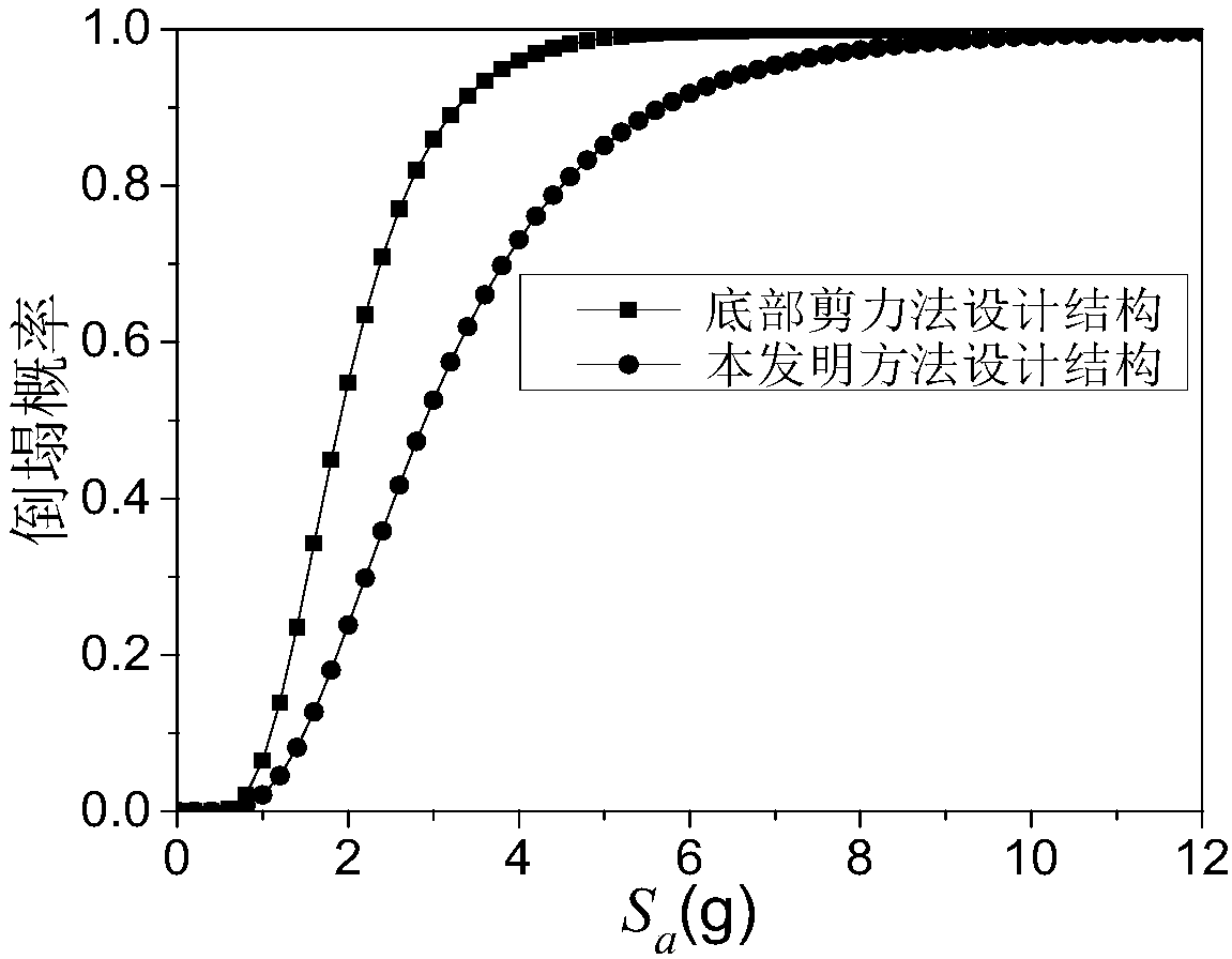

specific Embodiment approach 1

[0018] Specific embodiment one: a kind of anti-seismic design method that improves building structure anti-collapse ability comprises the following steps:

[0019] Step 1: Determine the number of floors N and site type of the building structure to be designed according to the design requirements and location; select the building structure system (such as reinforced concrete frame, steel frame, masonry structure, etc.), and design according to the conventional structure Method to preliminarily design the size of structural components and estimate the basic period T of the building structure 1 ;

[0020] Step 2: Using the bottom shear force method given in the code for seismic design of buildings (such as the current "Code for Seismic Design of Buildings" GB50011-2010), calculate the seismic action on each floor of the structure and find The interstory shear force of each layer (its value is the same as the yield strength of each layer), calculate the bottom shear force V of th...

specific Embodiment approach 2

[0026] Specific embodiment two: the difference between this embodiment and specific embodiment one is: obtain new building structure bottom shear force V in the described step 4 base Specifically:

[0027] V base =λ base ×S 2

[0028] where the S 2 is the sum of the yield strength of each layer of the structure calculated using the bottom shear method considering the additional force on the top of the structure, λ base is the new shear coefficient at the bottom of the structure.

[0029] Other steps and parameters are the same as those in Embodiment 1.

specific Embodiment approach 3

[0030] Specific implementation mode three: the difference between this implementation mode and one of the specific implementation modes one to two is: the λ base Specifically:

[0031]

[0032] which stated Adjustment factor for bottom shear.

[0033] Other steps and parameters are the same as one of the specific implementation modes 1 to 2.


PUM


Abstract

The invention relates to an anti-seismic design method for improving the anti-collapse capacity of an architectural structure. The method solves the problems that the anti-collapse capacity of medium and low-layer architectural structures is weak and the anti-collapse capacity of each floor of the architectural structures is not sufficiently exerted in the prior art. The method comprises the steps of: 1, selecting an architectural structure system, designing the sizes of architectural structure members and estimating the basic cycle T1 of the architectural structure; 2, calculating the seismic action borne by each layer of the structure, solving the interlayer shear of each layer, and calculating the ratio lambda 1 of the base shear V1 of the architectural structure to the yield strength sum S1 of the layers of the structure; 3, determining the layer ductility mu of the architectural structure; 4, obtaining new base shear Vbase of the architectural structure; and 5, recalculating the seismic action borne by each layer of the structure, and solving the interlayer shear of each layer according to the seismic action of each layer. The method is applied in the field of anti-seismic design.

Description

technical field [0001] The invention relates to an anti-seismic design method of building structures. Background technique [0002] The investigation of earthquake damage found that the collapse resistance of middle and low-rise building structures is weaker than that of high-rise building structures. In the design code, only important and complex building structures are subject to collapse resistance check calculation based on nonlinear time-history analysis method, while the collapse resistance check calculation is not required for ordinary building structures with large volume and wide area. Therefore, it is necessary to pay more attention to the anti-seismic collapse ability of middle and low-rise building structures, and study the design methods that can improve their anti-collapse ability. [0003] The calculation of earthquake action is the premise of the seismic design of building structures. Its purpose is to obtain the lateral loads on each floor of the building s...

Claims


Application Information

Patent Timeline
Patent Type & Authority Patents(China)
IPC IPC(8): E04H9/02
CPCE04H9/02
Inventor 李爽余斌高梦梦翟长海谢礼立
Owner HARBIN INST OF TECH
Learn More