A kind of inverted u-tube differential pressure meter and its method
A technology of U-shaped tube and differential pressure gauge, which is applied in the field of differential pressure gauge, can solve the problems of pressure gauge reference error, poor precision, large error, etc., and achieve the effect of increasing the pressure resistance value, convenient installation and use, and small error
Active Publication Date: 2022-06-03
MINZU UNIVERSITY OF CHINA
View PDF4 Cites 0 Cited by
- Summary
- Abstract
- Description
- Claims
- Application Information
AI Technical Summary
Problems solved by technology
The problem with this method is that there may be errors in the reference of the pressure gauge, especially the pressure gauge for measuring high pressure, which has a large range, poor accuracy, and greater errors
If the differential pressure of the two sections is small, the differential pressure value is even submerged by the error, and an accurate differential pressure value cannot be obtained
Method used
View moreImage
Smart ImageViewing Examples
Examples
Embodiment Construction
Login to View More PUM
 Abstract
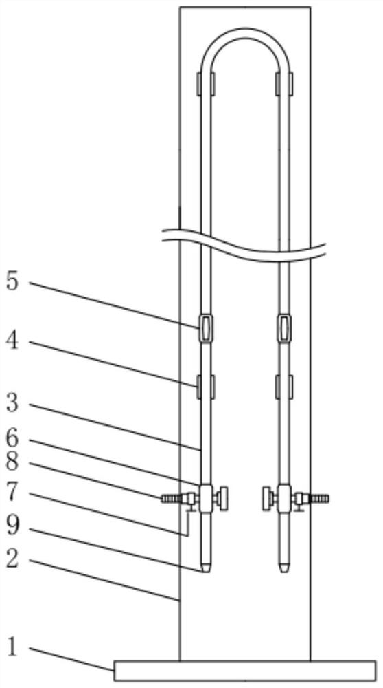
The invention discloses an inverted U-shaped tube differential pressure gauge, which comprises a base and a bracket. The bracket is installed on the base. The inverted U-shaped tube is fixed on the front of the bracket through a clamp. Both sides of the inverted U-shaped tube are symmetrically arranged with stop valves. , a three-way valve is installed below the stop valve; one branch of the three-way valve is connected to the inverted U-shaped pipe, and the other two branches are respectively connected to the discharge port and the test interface; a ball valve is installed at the discharge port, and a Net plug; a scale is set on the bracket; the inverted U-shaped tube is made of plexiglass. The present invention also provides a method for using the inverted U-shaped tube differential pressure gauge. The present invention can use clear water or other liquids as the medium, has no influence on the environment and the pipeline, and at the same time increases the anti-pressure value of the inverted U-shaped pipe, ensuring safe use, convenient installation and use, high precision and small error; adopts vertical design , It is not in direct contact with the measured pipeline during measurement, and will not be affected by the vibration of the pipe wall. It is suitable for accurately measuring the low pressure difference of high pressure pipelines.
Description
A kind of inverted U-tube differential pressure gauge and method technical field The present invention relates to a kind of differential pressure gauge that is measured when the internal fluid of pipeline is conveyed, relate in particular to a kind of inverted U-shaped Tube differential pressure gauge and method of use. Background technique In the pipeline fluid transportation process, in order to calculate the resistance loss of the pipeline, it is necessary to measure the difference between the different sections of the pipeline. pressure difference. The conventional devices for measuring differential pressure are U-tube differential pressure gauges or dual pressure gauges. [0003] The U-tube differential pressure gauge is widely used due to its simple structure, ease of manufacture, ease of use, and high measurement accuracy. application. U-tube differential pressure gauges are generally used for measurement in low pressure environments. U-tubes are made of glas...
Claims
Login to View More Application Information
Patent Timeline
 Patent Type & Authority Patents(China)
IPC IPC(8): G01L13/04
CPCG01L13/04
Inventor 夏建新符瑜曹斌任华堂
Owner MINZU UNIVERSITY OF CHINA
Features
- R&D
- Intellectual Property
- Life Sciences
- Materials
- Tech Scout
- Unparalleled Data Quality
- Higher Quality Content
- 60% Fewer Hallucinations
Learn More Browse by: Latest US Patents, China's latest patents, Technical Efficacy Thesaurus, Application Domain, Technology Topic, Popular Technical Reports.
© 2025 PatSnap. All rights reserved.Legal|Privacy policy|Modern Slavery Act Transparency Statement|Sitemap|About US| Contact US: help@patsnap.com

