
High voltage test mechanism used for producing flat bridge and working method thereof

A technology of high-voltage testing and flat bridge, which is applied in the field of high-voltage testing institutions, can solve problems such as the inability to guarantee long-term efficient and stable testing, the complicated operation process of high-pressure testing institutions, and high manufacturing and operating costs, so as to achieve the goal of not being prone to deviations and failures, The effect of high test efficiency and low manufacturing and operating costs

Inactive Publication Date: 2017-01-18
TAICANG GAOCHUANG ELECTRICAL TECH
View PDF4 Cites 0 Cited by
  • Summary
  • Abstract
  • Description
  • Claims
  • Application Information

AI Technical Summary

Problems solved by technology

[0004] 1. The overall structure and operation process of the high-voltage testing mechanism are very complicated, and the load requirements are high, the maintenance is very cumbersome, and the manufacturing and operating costs are high;
[0005] 2. The degree of automation is low, the operation of personnel is complicated, and the test efficiency is low;
[0006] 3. Deviations and failures are prone to occur during operation, and long-term efficient and stable testing cannot be guaranteed

Method used


Image

  • High voltage test mechanism used for producing flat bridge and working method thereof
  • High voltage test mechanism used for producing flat bridge and working method thereof
  • High voltage test mechanism used for producing flat bridge and working method thereof

Examples


Embodiment 1

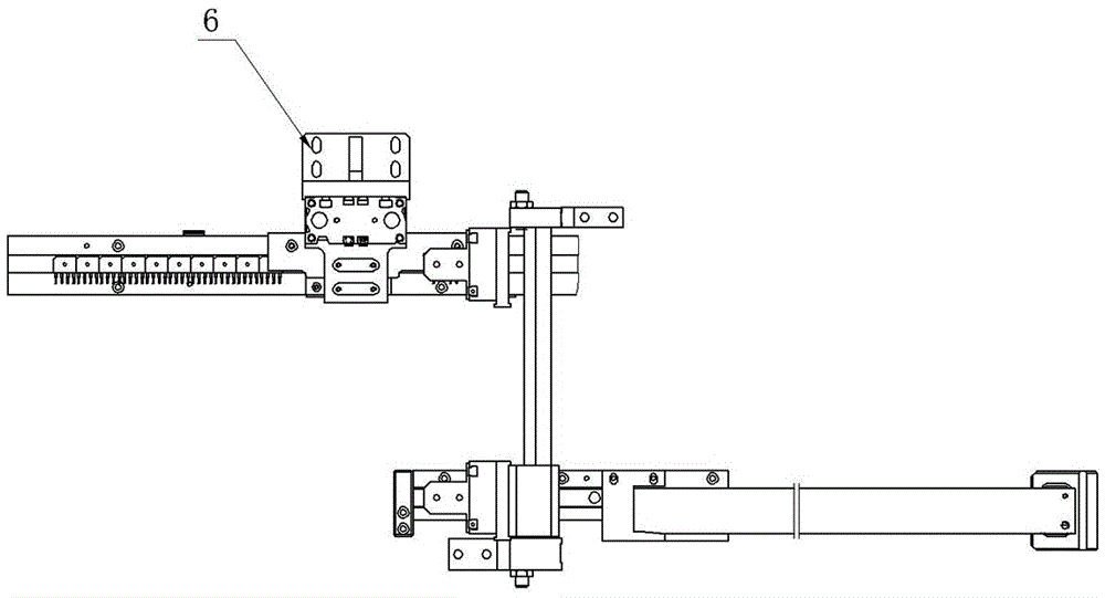
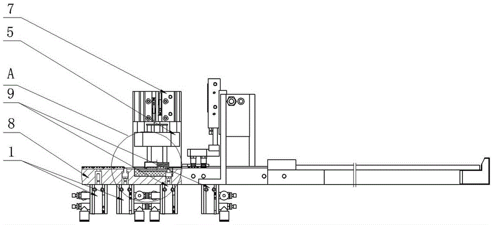
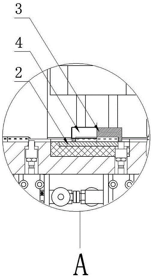
[0030] Such as Figure 1-Figure 3 As shown, a high-voltage test mechanism for producing flat bridges in this embodiment includes: switch cylinder 1, lower electrode 2, upper inner electrode 3, upper outer electrode 4, high-voltage test seat 5, high-voltage test cylinder seat 6, High pressure test cylinder 7, track 8 and material blocking cylinder 9.

[0031] The connection relationship of the above-mentioned components is as follows: the double switch cylinder 1 and the retaining cylinder 9 are all fixed on one side of the track 8, the track 8 and the high-voltage test cylinder seat 6 are all fixed on the frame panel, and the high-voltage test seat 5 is installed at the lower end of the high-voltage test cylinder 7; the upper inner electrode 3 and the upper outer electrode 4 are installed side by side on the high-voltage test seat 5, and an insulating layer is provided between the lower electrode 2 and the track 8. Wherein the upper inner electrode 3, the upper outer electrod...


PUM


Abstract

The invention discloses a high voltage test mechanism used for producing a flat bridge, and mainly relates to the technical field of bridge rectifiers. The high voltage test mechanism comprises a double-switch cylinder, a lower electrode, an upper internal electrode, an upper external electrode, a high voltage test base, a high voltage test cylinder base, a high voltage test cylinder, a track and a material blocking cylinder. The double-switch cylinder and the material blocking cylinder are fixed at one side of the track. The track and the high voltage test cylinder base are fixed on a rack panel. The high voltage test base is installed at the lower end of the high voltage test cylinder. The upper internal electrode and the upper external electrode are installed on the high voltage test base in parallel. An insulating layer is arranged between the lower electrode and the track. The high voltage test mechanism is quite simple in overall structure and operation process, convenient and rapid in maintenance, low in cost, high in degree of automation and simple in manual operation and can guarantee long-time and high-efficiency stable testing. The invention also discloses a working method of the high voltage test mechanism used for producing the flat bridge.

Description

technical field [0001] The invention relates to the technical field of bridge rectifiers, in particular to a high-voltage testing mechanism for producing flat bridges and a working method of the high-voltage testing mechanism. Background technique [0002] The bridge rectifier is made of four rectifying silicon chips connected in a bridge type and packaged externally with insulating plastic. There are many types of bridge rectifiers: flat, round, square, bench-shaped (in-line and patch), etc., among which the flat bridge is a kind of bridge rectifier. [0003] In recent years, with the continuous development of science and technology, related industries have higher and higher technical requirements for flat bridges. However, the existing high-voltage testing institutions for the production of flat bridges still have the following defects: [0004] 1. The overall structure and operation process of the high-voltage testing mechanism are very complicated, and at the same tim...

Claims


Application Information

Patent Timeline
Patent Type & Authority Applications(China)
IPC IPC(8): G01R31/01
CPCG01R31/01
Inventor 程嘉义
Owner TAICANG GAOCHUANG ELECTRICAL TECH
Learn More