

Full-slide damping capacitive micromachined gyroscope
A capacitive micro-mechanical and synovial damping technology, which is applied in the direction of steering induction equipment, etc., can solve the problems of reducing the sensitivity characteristics of micro-machine gyroscopes, and achieve the effect of improving the sensitivity characteristics.
Inactive Publication Date: 2013-01-16
NORTHWESTERN POLYTECHNICAL UNIV
View PDF1 Cites 3 Cited by
- Summary
- Abstract
- Description
- Claims
- Application Information
AI Technical Summary
Problems solved by technology
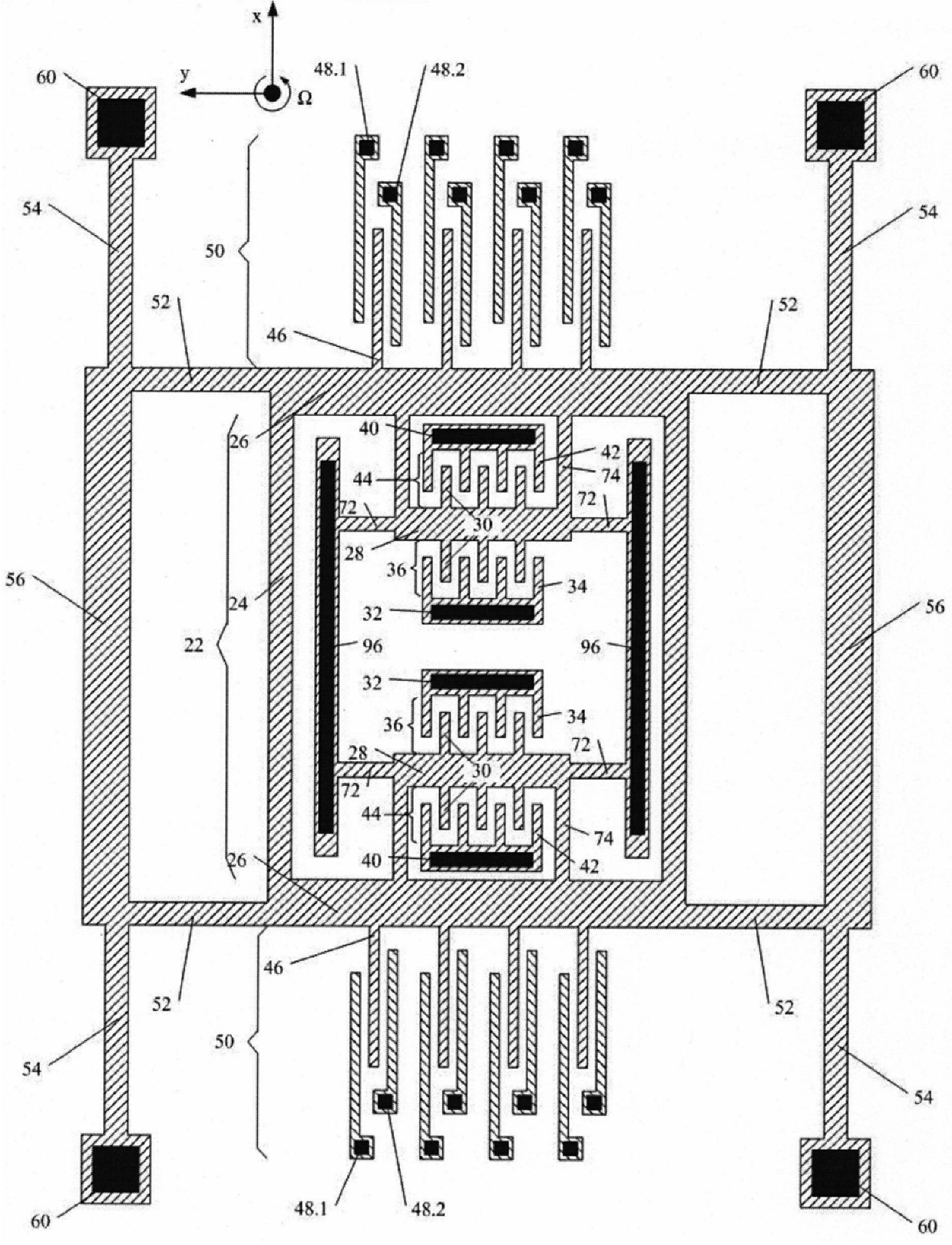
However, when the gyroscope is in operation, when the detection comb 46 moves in the Y direction, the left variable-pitch comb 48.1 and the right variable-pitch comb 48.2 form pressure-film damping, and the pressure-film damping formed between them will reduce the micromechanical gyroscope. Sensitivity characteristics
Method used
View moreImage
Smart ImageViewing Examples

Examples
Embodiment Construction
Login to View More PUM
 Abstract
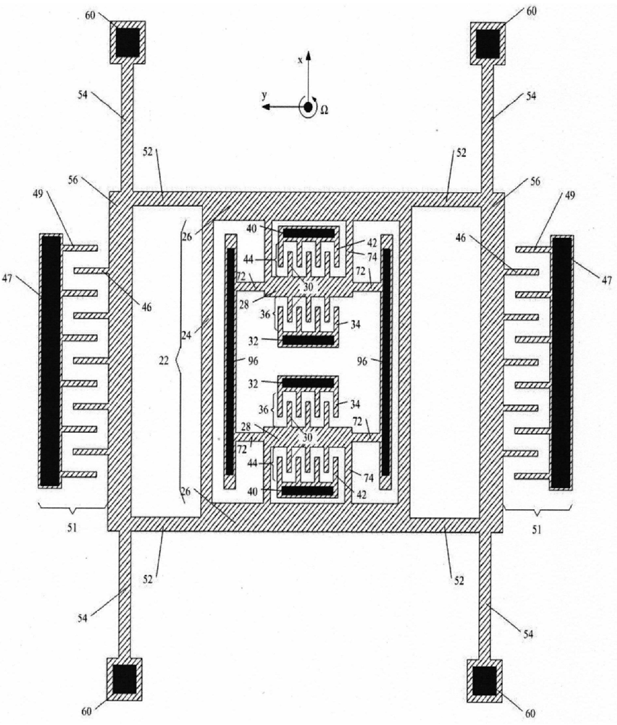
The invention discloses a full synovial film damping capacitive micro-mechanical gyroscope, which is used to solve the gyroscope sensitivity characteristics of the pressure film damping between the gyroscope detection comb teeth and the left and right variable-pitch comb teeth when they move along the Y direction in the prior art The problem of influence is characterized in that the variable-spacing sensitive capacitor pair composed of the detection comb and the left and right variable-spacing combs in the original structure is cancelled, and a group of them are respectively protruded from the outside of the non-deformed connecting beam (56) instead. The detection comb (46), the comb detection electrode pair (51) formed by the detection electrode comb (49) and the detection comb (46), is fixed on the substrate through the anchor point on the detection electrode (47). In this way, the gyroscope not only realizes the decoupling between the driving mode and the sensitive mode during the working process, but also forms a synovial film damping between the detection comb (46) and the detection electrode comb (49) when it moves in the Y direction, thereby The production and influence of pressure film damping are avoided, therefore, the sensitivity characteristics of the gyroscope are significantly improved while realizing the decoupling of the gyroscope.
Description
Full-slide damping capacitive micromachined gyroscope technical field The invention relates to a capacitive micro-mechanical gyroscope with full synovial film damping. Background technique The capacitive micro-mechanical gyroscope is made of silicon-based semiconductor technology. It has the characteristics of small size, high reliability, and batch manufacturing. It can be used for angular velocity measurement and attitude stabilization of moving objects such as aircraft, missiles, and automobiles. Micromechanical gyroscopes are all based on Coriolis force to detect angular velocity, and include two mutually perpendicular working modes: driving mode and sensitive mode. Referring to Figure 2, in the patent document "Capacitive Micromechanical Gyroscope" with application number 200510096227.1 and publication number CN1749693, Northwestern Polytechnical University proposed a capacitive micromechanical gyroscope, which uses a decoupling beam structure to solve the gyroscope ...
Claims
Login to View More Application Information
Patent Timeline
 IPC IPC(8): G01C19/56
Inventor苑伟政谢建兵常洪龙蒋庆华
OwnerNORTHWESTERN POLYTECHNICAL UNIV